


Physical Characteristics
152607 1–7
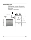
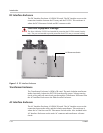
Main Inverter Enclosure
The PV225S Main Inverter Enclosure is NEMA-3R rated and contains the power
distribution panel, the converter control unit (CCU2), and the power electronics
matrices. Also found within the Main Inverter Enclosure are some of the system
protection devices (such as the sense and control power fuses).
Power Distribution Panel
This panel contains many of the Electromechanical, protective, and control power
components necessary to support the operation of the PV225S.
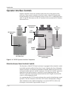
Converter Control Unit (CCU2)
The CCU2 is a Digital Signal Processor (DSP) based control board that performs
numerous control and diagnostic functions associated with PV225S operation. Its
most significant tasks are control of PV225S electromechanical components and
power electronics converters, signal conditioning for high voltage signal inputs
and communication with the Universal Front Panel Control Unit, and system
sensors. The CCU2 also contains the necessary DC power supplies to support its
operation.
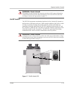
Power Electronics Matrices
The power electronics converters are located at the top of the PV225S main
inverter enclosure. Both the left and right matrices are comprised of six switching
transistors (IGBTs), transistor gate drive electronics, a laminated power bus, DC
capacitor bank, and an aluminum extrusion heatsink with a cooling fan. The fans
are located above each matrix heatsink.
The PV array is tied logically to the matrices DC bus within the DC interface
enclosure. The embedded CCU2 control unit manages the transfer of power
between the DC bus and the utility grid by sending digitized gating signals to the
IGBTs for producing a high-fidelity, sinusoidal output.
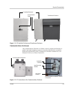
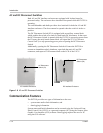
Inductor Enclosure
The Inductor Enclosure is NEMA-3R rated. It contains the necessary filter
components to ensure the PV225S line current meets IEEE-519 (1992, Standard
Practices and Requirements for Harmonic Control in Electrical Power Systems)
and UL 1741 (2001, Static Inverters and Converters for use in Independent Power
Systems) harmonic distortion requirements. Mounted on both the right and left
side of the lower enclosure are inductor fans to allow cooling of the line filter
components within. This enclosure also serves as the mounting base for the
PV225S Main Enclosure.