


E6581090
H-1
8
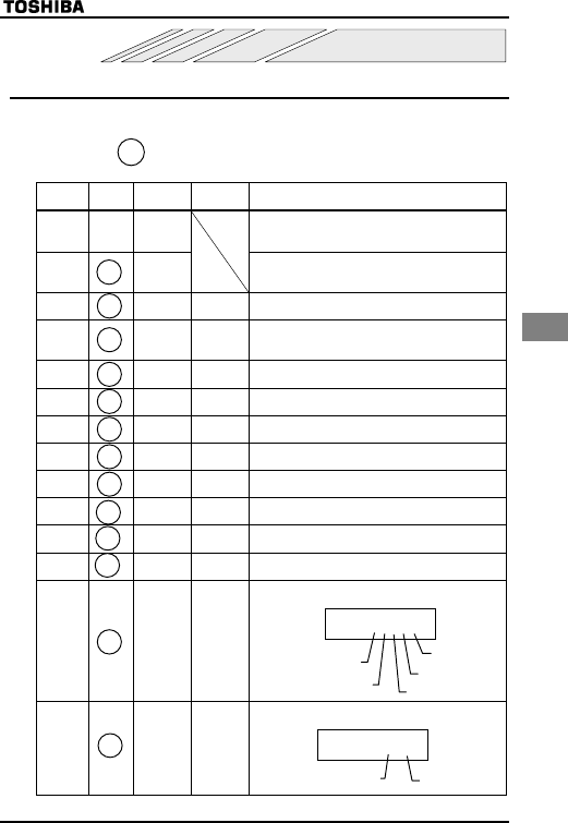
8. Monitoring the operation status
8.1 Status monitor mode
In this mode, you can monitor the operation status of the inverter.
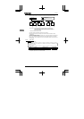
To display the operation status during normal operation:
Press the
key twice.
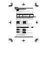
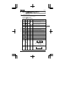
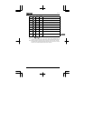
Setting procedure (eg. operation at 60Hz)
Item
displayed
Key
operated
LED
display
Communication
No.
Description
The operation frequency is displayed (during operation).
(When the standard monitor display selection parameter
H is set at 0 [operation frequency])
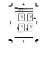
Parameter
setting
mode
CWJ
The first basic parameter "History (CWJ)" is displayed.
Direction of
rotation
HTH FE01
The direction of rotation is displayed.
(H : forward run, T : reverse run)
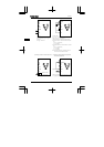
Operation
frequency
command
H FE02 The operation frequency command value is displayed.
Load
current
E FE03
The inverter output current (load current) is displayed. (Default
setting : unit %)
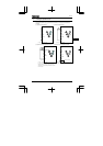
Input
voltage
[ FE04
The inverter input (DC) voltage is displayed.
(Default setting: unit %)
Output
voltage
R FE05
The inverter output voltage is displayed. (Default setting:
unit %)
To rqu e
current
Y FE20 The torque current is displayed in %.
PI feedback F FE22 The PI feedback value is displayed. (Unit: frequency)
Inverter
load factor
N FE27 The inverter load factor is displayed in %.
Output
power
J FE30 The inverter output power is displayed in %.
Operation
frequency
Z FE00 The operation frequency is displayed.
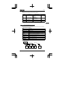
Input
terminal
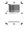
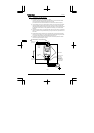
C!! FE06
The ON/OFF status of each of the control signal input terminals
(F, R, S1, S2 and VI/S3) is displayed in bits.
ON:
OFF: _
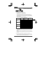
Output
terminal
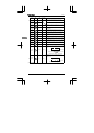
Q FE07
The ON/OFF status of each of the control signal output
terminals (FM/OUT and FL) is displayed in bits.
ON:
OFF: _
(Continued overleaf)
MON
MON
Note 1
MON
▲
▲
Note 2
▲
Note 3
▲
▲
▲
▲
▲
▲
▲
▲
C
!!
Input terminal
VI/S3
Input terminal S2
Input terminal F
Input terminal R
Input terminal
S1
Output terminal FL
Output terminal
FM/OUT
Q
Note 3