


E6581090
B-10
2
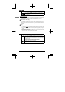
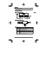
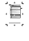
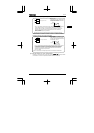
Output terminals cannot be switched between sink logic and source logic.
See the figures below for connection to sink logic and source logic terminals.
CC
FM/OUT
Source logic
Common
Input
15V
DC
CC
FM/OUT
Sink logic
Inverter
Programmable
controller
Common
Input
+
Power supply
P15
Inverter
Programmable
controller
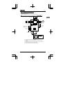
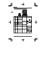
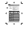
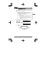
■Switching the input terminal logic between sink and source
Input terminals of the VF-nC1 inverter can be switched between sink logic and source logic, using
the H parameter.
When switching between sink logic and source logic, do it before connecting cables to inverter’s
control circuit terminals. When the confirmation message G or G is displayed after
switching between sink logic and source logic, using the H parameter, reset the inverter,
using the operation panel, by turning the power off, or by inputting a reset signal from an external
control device.
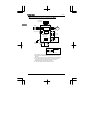
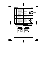
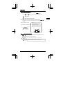
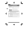
■Switching the VI/S3 terminal between logic input and analog input
The VI/S3 terminal of the VF-nC1 inverter can be switched between contact input and analog
input by changing a parameter setting. When switching between contact input and analog input,
do it before connecting cables to inverter’s control circuit terminals (H).
If switching between contact input and analog input is done after cable connection, the inverter
and/or the external device connected might be damaged. Before turning on the inverter, make
sure all cables are connected correctly to the control terminals.
When using the VI/S3 terminal as an contact input terminal (sink logic), be sure to insert a
resistor* between the P15 and VI/S3 terminals. (Recommended resistance: 4.7kΩ-1/4W).
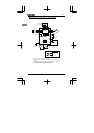
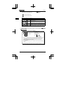
■Switching the FM/OUT terminal between meter output (PWM output) and open
collector output
The FM/OUT terminal of the VF-nC1 inverter can be switched between meter output (PWM
output) and open collector output.
When switching between meter output (PWM output) and open collector output, do it before
connecting an external device to the inverter. After switching from meter output (PWM output) to
open collector output, and vice versa, check using the HOUN parameter to be sure that the
desired function is assigned to the FM/OUT terminal, and then turn the power off. After the
completion of cable connection, turn the power back on. If switching between meter output and
open collector output is done after cable connection, the inverter might be damaged.