


E6581090
K-3
11
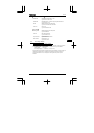
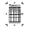
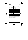
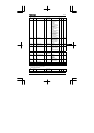
11.3 Extended parameters
• Input/output parameters
Title
Communication
No.
Function Unit
Minimum setting
unit Panel/
Communication
Adjustment range
Default
setting
User
setting
Reference
H 0100 Low speed signal
output frequency
Hz 0.1/0.01 0.6-HJ 0.6 6.1.1
H
0101 Speed-reach setting
frequency
Hz 0.1/0.01 0.0-HJ 0.0 6.1.2
H
0109 Analog input/logic
input function
selection (VI/S3)
--0:Voltage signal input
(0-5 or 10V)
1:Current signal input
(4-20mA)
2:Contact input
06.2.1
H
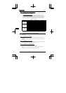
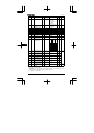
0110 Always active
function selection
--0~40, 49, 54~57 1
(ST)
6.2.2
H
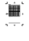
0111 Input terminal
selection 1 (F)
--0~40, 49, 54~57 2
(F)
6.2.3
H
0112 Input terminal
selection 2 (R)
--0~40, 49, 54~57 3
(R)
6.2.3
H
0113 Input terminal
selection 3 (S1)
--0~40, 49, 54~57 6
(SS1)
6.2.3
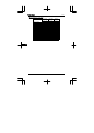
H 0114 Input terminal
selection 4 (S2)
--0~40, 49, 54~57 7
(SS2)
6.2.3
H 0115 Input terminal
selection 5 (VI/S3)*5
--5-17 8
(SS3)
6.2.3
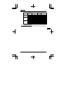
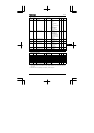
H 0127 Sink/Source selection - - 0: Sink 100: Source
1-99,101-200: Disabled
*2 6.2.5
H 0130 Output terminal
selection 1
(FM/OUT)*6
--0-13 4
(LOW)
6.2.6
H
0132 Output terminal
selection 3 (FL)
--0-13 10
(FL)
6.2.6
H
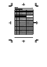
0170 Base frequency 2 Hz 0.1/0.01 25-200 *2 6.3.1
H 0171 Base frequency
voltage 2
V1/150-500 *2 6.3.1
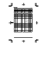
H 0172 Torque boost 2 % 0.1/0.1 0.0-30.0 *3 6.3.1
H
0173 Motor thermal
protection level 2
%1/130-100 100 6.3.1
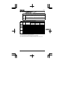
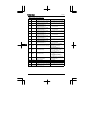
*2: The value is changed according to the set-up parameter condition.
(VFNC1 (S)-□□□□P□-W type)
FH:80, UL80, VL:60, F127:0, F170:60, F171:200, F204:80, F409:200, F417:1710 for VFNC1 (S)-□□□
□P□ type.
*3:Parameter values vary depending on the capacity. Refer to page K-8.
*5: This function is enabled if F109 is set at 2 (logic input).
*6: This function is enabled if FMSL (open collector output) is set at 1.