


E6581090
F-9
6
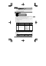
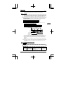
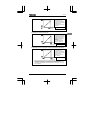
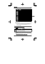
1) Adjustment of 0~10Vdc voltage input
VI terminal
•
The output frequency
with respect to the
voltage input is adjusted
according to the selected
reference point.
•
Gradient and bias can be
set easily.
H
100 (%)
10V Voltage signal
H
0 (Hz)
H
0 (%)
0
H
80 (Hz)
H
: 0 (voltage input)
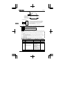
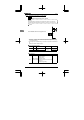
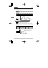
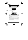
2) Adjustment of 4~20mAdc current input
VI/S3 terminal
• The output frequency with
respect to the current input
is adjusted according to the
selected reference point.
•
Gradient and bias can be
set easily.
•
Set H to to
produce a current input
between 0 and 20mA.
H
100 (%)
20mA
Current signal
H
0 (Hz)
H
20 (%)
4
H
80 (Hz)
H
:1(current input)
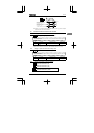
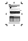
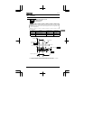
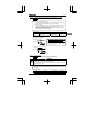
3) Adjustment of 0~5Vdc voltage input and external potentiometer (P5-VI/S3-CC)
VI/S3 terminal
*When an external potentiometer is connected to the inverter via the P5V terminal, it is
necessary to set the
H
(= 47 ~ 50 approx.) a voltage drop might occur,
depending on the resistance of the resistor connected. Therefore, if there is no need
to increase the output frequency above the frequency set with H, use H
for this adjustment.
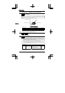
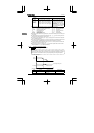
•
The output frequency
with respect to the
voltage input is adjusted
according to the selected
reference point.
•
Gradient and bias can
be set easily.
H
47~50 (%) *
5V voltage signal
H
0 (Hz)
H
0 (%)
0V
H
80 (Hz)
H
: 0 (voltage input)