


E6581090
B-7
2
2.3 Description of terminals
2.3.1 Main circuit terminals
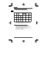
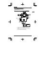
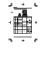
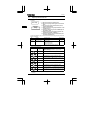
This diagram shows an example of wiring of the main circuit. Use options if necessary.
■Power supply and motor connections
or or
VF-nC1
Power
supply
E
R/L1 S/L2 T/L3 U/T1 V/T2W/T3
Motor
Powerlines are
connected to R, S and T.
Motorlines are connected
to U, V and W.
No-fuse
breaker
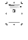
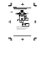
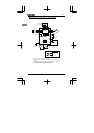
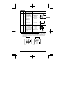
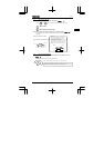
■Connections with peripheral equipment
Motor
Power
supply
Inverter
DC reactor
No-fuse
breaker
R/L1
S/L2
T/L3
PC/- PA/+
PO
V/T2
U/T1
W/T3
IM
Magnetic
contactor
Input
reactor
Noise reduction
filter
Zero-phase
reactor
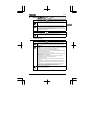
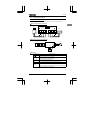
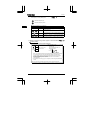
■Main circuit
Terminal symbol Terminal function
Grounding terminal for connecting inverter case. 2 grounding terminals.
R/L1, S/L2,
T/L3
100V class: 1-phase 100V to 115V - 50/60Hz
200V class: 1-phase 200V to 240V - 50/60Hz, 3-phase 200V-240V - 50/60Hz
*1-phase series have R/L1 and S/L2 terminal.
U/T1, V/T2,
W/T3
Connect to a (3-phase induction) motor
PC/- This is a negative potential terminal in the internal DC main circuit.
PO, PA/+
Terminals for connecting a DC reactor (DCL: optional external device).
Shorted when shipped from the factory. Before installing DCL remove the short
bar.
1-phase 100V models cannot be used with DC reactors. 1-phase 200V models
for Europe are not provided with PO terminal.