


E6581090
B-9
2
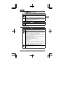
Ter min a
l symbol
Input/
output
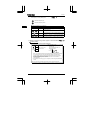
Function Specifications Inverter internal circuit
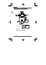
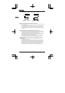
FM/
OUT
Output
Multifunction programmable
output.
Standard default setting:
output frequency.
Meters connectable to
FM/OUT: 1mAdc full-scale
ammeter or 7.5Vdc (10Vdc) -
1mA full-scale voltmeter (PWM
output).
Possible to switch to
programmable open collector
output by changing a
parameter.
1mA full-scale
DC ammeter or 7.5Vdc
(10Vdc) full-scale
DC voltmeter
Open collector output:
24Vdc-50mA
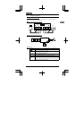
P15 Output 15Vdc power output. 15Vdc-100mA
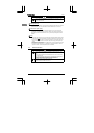
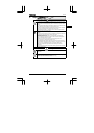
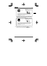
FLA
FLB
FLC
Output
Multifunction programmable
relay contact output. Contact
ratings: 250Vac - 2A (cos
φ
=1),
30Vdc - 1A, 250Vac - 1A
(cos
φ
=0.4). Standard default
setting: Monitoring of status of
inverter’s protection function.
Activation of the protection
function causes circuit FLA-
FLC to close and circuit FLB-
FLC to open.
250Vac-2A
(cos
φ
=1):
at resistance load
30Vdc-1A
250Vac-1A (cos
φ
=0.4)
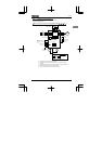
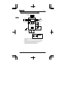
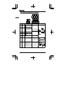
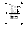
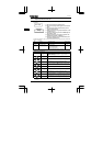
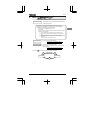
■Sink logic (negative common)/source logic (positive common)
⋅⋅⋅ Logic switching of input output terminals
Current flowing out turns control input terminals on. These are called sink logic terminals. (For all
models except models with a built-in noise filter, control input terminals are factory-set to sink
logic.) The general used method in Europe is source logic in which current flowing into the input
terminal turns it on.
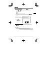
Source logic
Inverter
P15
F
Programmable
controller
Common
Output
Input
15V
DC
Sink logic
Inverter
F
CC
Programmable
controller
Common
Output
Input
15V
DC
FM/OUT
◎
47
3.4K
+15V
+15V
◎
P15
+15V
FLA
◎
+15V
FLC
FLB
◎
◎
FL
100