Groundsmaster 4000--D/4010--D Page 5 -- 49 Electrical System
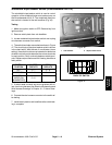
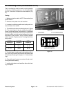
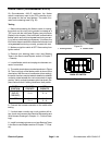
8. Connect multimeter(ohms setting)leads torelay ter-
minals 30 and 87A. Apply +12 VDC to terminal 85. The
relay should make and break c ontinuity between termi-
nals 30 and 87A as +12 VDC is applied and removed
from terminal 85.
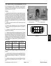
9. After testing, disconnect voltage and multimeter test
leads fromthe relay terminals. Securerelay to mounting
bracket and connect wire harness connector to relay.
10.Secure all removed c omponents to machine.
11.Connect positive (+) cable first to battery and then
connect negative (--) cable to b a ttery (see Battery Ser-
vice in the Service and Repairs section of this chapter).
Electrical
System


