9-4-22 BRASH HOLDER
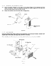
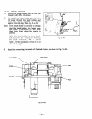
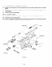
(1) Mount the brash holder base on the rear
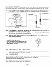
bracket with PI5 x 10 screws.
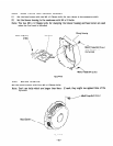
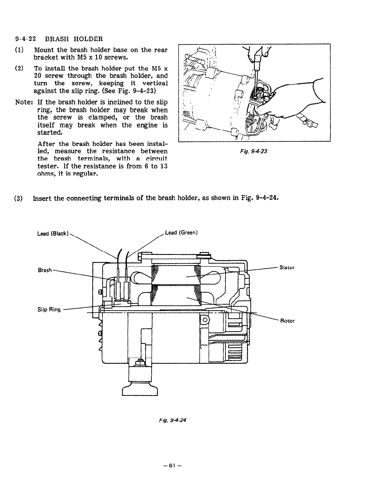
(2) To install the brash holder put the M5 x
20 screw through the brash holder, and
turn the screw, keeping it vertical
against the slip ring. (See Fig. 9-4-23)
Note: If the brash holder is inclined to the slip
ring? the brash holder may break when
the screw is clamped, or the brash
itself may break when the engine is
started.
After the brash holder has been instal-
led? measure the resistance between
the brash terminals, with a circuit
tester. If the resistance is from 6 to 13
ohms, it is regular.
I
Fig. 94-23
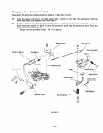
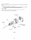
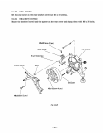
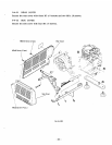
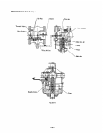
(3) Insert the connecting terminals of the brash holder, as shown in Fig. 9-4-24.
Lead (Black)
\
/
Lead (Green)
Stator
Rotor
Fig. 94-24
-61-


