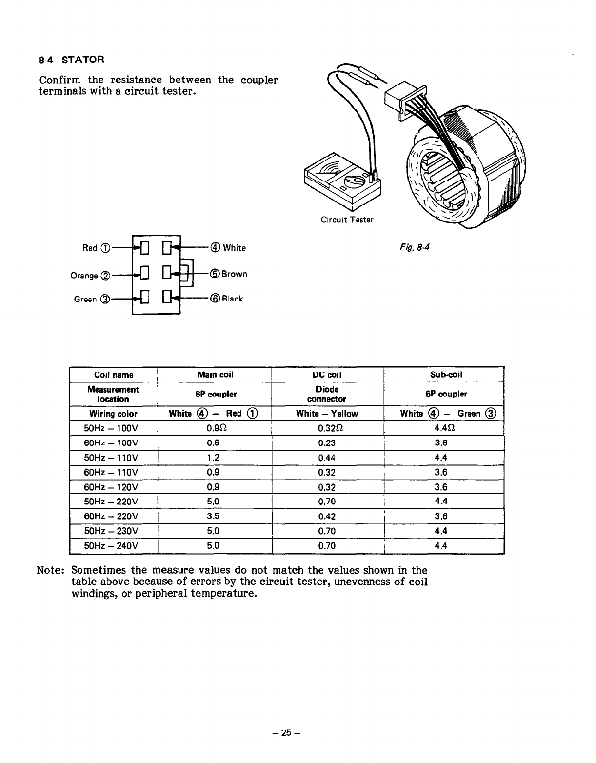
84 STATOR
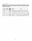
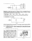
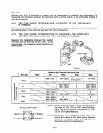
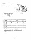
Confirm the resistance between the coupler
terminals with a circuit tester.
Red 3+-J a-@ White
Orange Q
Green @
OB
rown
@Black
Circuit Tester
F&. 8-4
Coil name I
Main coil
DC coil Sub-coil
Measurement ’ Diode
location
6P coupler
connector
6P coupler
Wiring color
White @ - Red @ 1
White - Yellow White @ - Green @
50Hz - IOOV 0.951
0.32Q
4.452
60Hz - 1oov 0.6
0.23
3.6
50Hz - I IOV !
1.2
0.44
I
4.4
60Hz - 1 IOV 0.9
I
0.32 3.6
60Hz - 120v 0.9
0.32
I
3.6
50Hz - 220V !
5.0
0.70
I
4.4
60HZ - 220V i
3.5
0.42
3.6
50Hz - 230V !
5.0
0.70 4.4
50Hz - 240V 5.0
0.70
I
4.4
Note: Sometimes the measure values do not match the values shown in the
table above because of errors by the circuit tester, unevenness of coil
windings, or peripheral temperature.
- 25 -


