


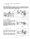
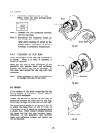
Fig. 8-l-l (a)
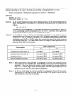
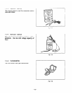
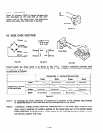
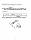
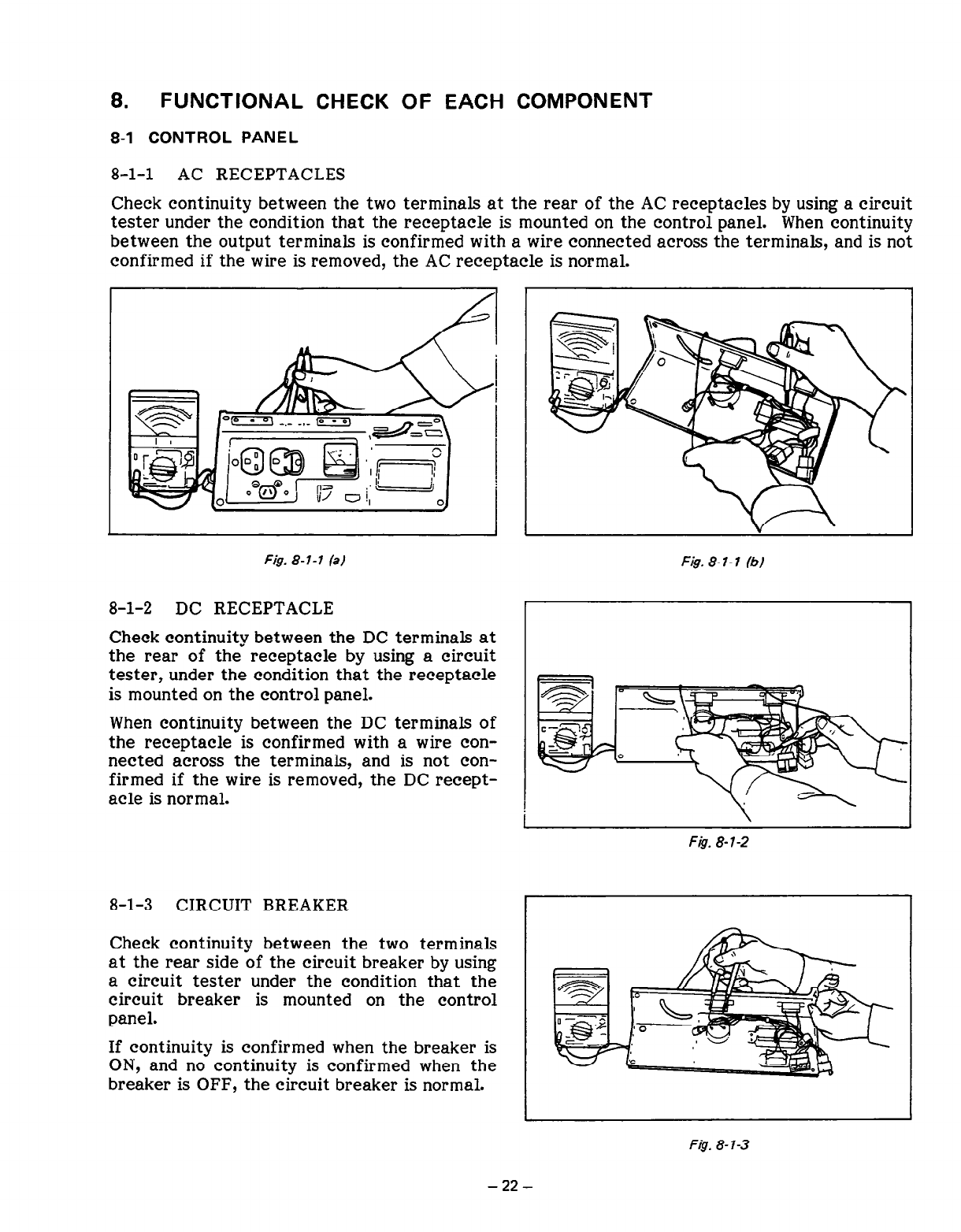
8-l-2 DC RECEPTACLE
Check continuity between the DC terminals at
the rear of the receptacle by using a circuit
tester, under the condition that the receptacle
is mounted on the control panel.
When continuity between the DC terminals of
the receptacle is confirmed with a wire con-
nected across the terminals, and is not con-
firmed if the wire is removed, the DC recept-
acle is normal.
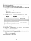
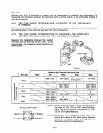
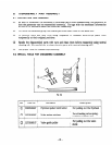
8-l-3 CIRCUIT BREAKER
Check continuity between the two terminals
at the rear side of the circuit breaker by using
a circuit tester under the condition that the
circuit breaker is mounted on the control
panel.
If continuity is confirmed when the breaker is
ON, and no continuity is confirmed when the
breaker is OFF, the circuit breaker is normal.
Fig. 8- I- 1 (b)
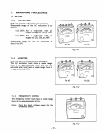
8.
FUNCTIONAL CHECK OF EACH COMPONENT
8-1 CONTROL PANEL
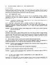
8-l-l AC RECEPTACLES
Check continuity between the two terminals at the rear of the AC receptacles by using a circuit
tester under the condition that the receptacle is mounted on the control panel. When continuity
between the output terminals is confirmed with a wire connected across the terminals, and is not
confirmed if the wire is removed, the AC receptacle is normal.
Fig. 8-l-2
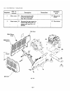
F&J. 8-7-3
-22-