


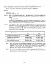
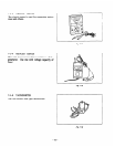
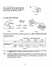
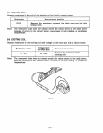
8-l-4 VOLTMETER
When AC voltage (1OOV) is loaded between the
two terminals on the rear side of the volt-
meter, and at the same time, the voltmeter
shows the value, the voltmeter is normal.
Fig. 8-l-4
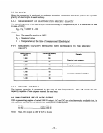
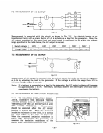
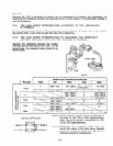
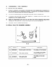
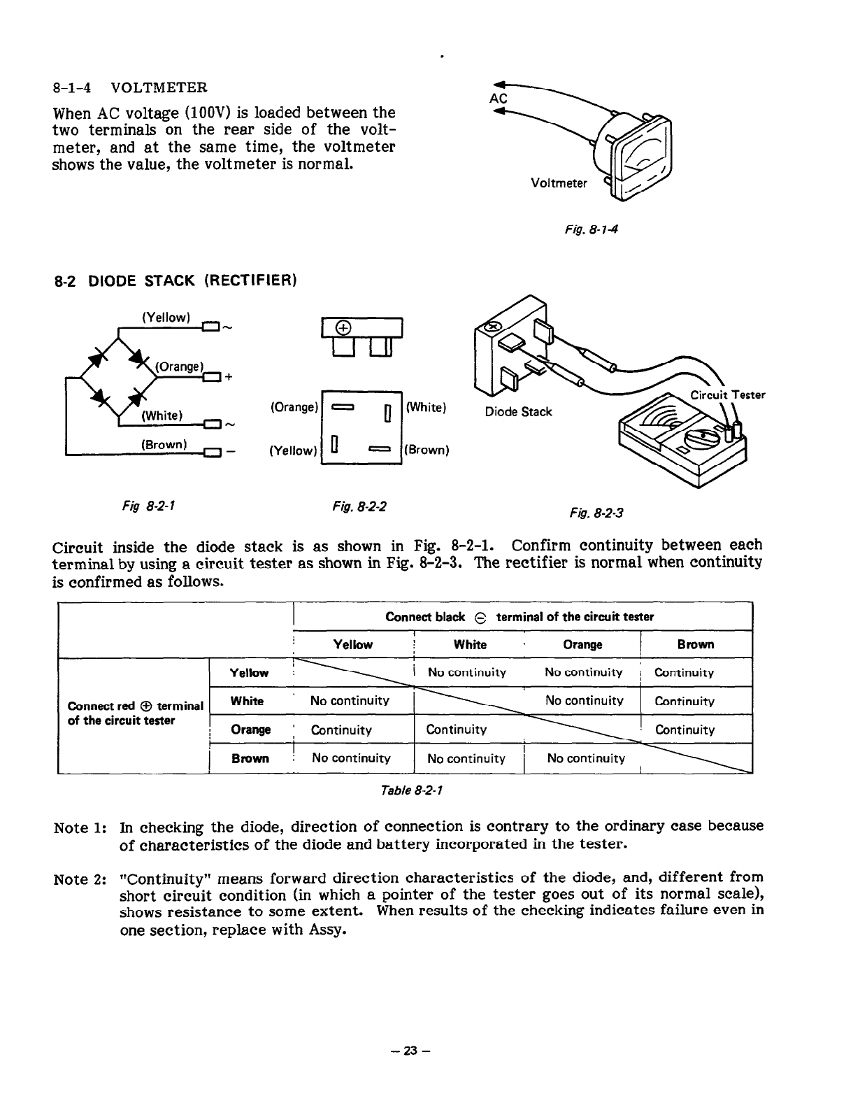
8-2 DIODE STACK (RECTIFIER)
(Orange) 0
0
cl
(White)
(Yellow)
0
- (Brown)
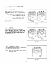
Fig 8-2-l
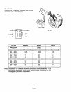
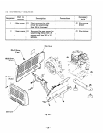
Fig. 8-2-2
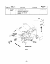
Fis. 8-2-3
Circuit inside the diode stack is as shown in Fig. 8-2-l.
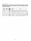
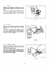
Confirm continuity between each
terminal by using a circuit tester as shown in Fig. 8-2-3. The rectifier is normal when continuity
is confirmed as follows.
I
Connect black s
terminal of the circuit tester
I
I
Yellow ; White . Orange Brown
No continuity ; Continuity
Connect red 0 terminal
of the circuit tester
I
Table 8-2- 1
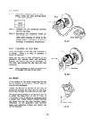
Note 1: In checking the diode, direction of connection is contrary to the ordinary case because
of characteristics of the diode and battery incorporated in the tester.
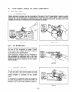
Note 2:
“Continuity” means forward direction characteristics of the diode, and, different from
short circuit condition (in which a pointer of the tester goes out of its normal scale),
shows resistance to some extent.
When results of the checking indicates failure even in
one section, replace with Assy.
- 23 -