


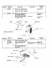
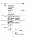
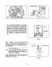
9-4-3 CONNECTING ROD
(1) Turn the crankshaft as far as the bottom dead point. Then, set the connecting rod, gently
striking the piston head until it touches the crankpin.
(2) Set the connecting rod cap according to the rod guide mark.
(3) Set the oil scraper in the magneto side.
Note: Be sure to use a new lock washer. Bed the washer carefully and correctly.
Note: When the connecting rod cap has been installed, manually turn the crankshaft to confirm
that
the connecting rod moves smoothly.
Note: The specified torque for installing the connecting rod cap is from 90 to 115 kg-cm.
Note: For details regarding the clearances between the piston, piston ring, and rod, see Table 9-
4-l.
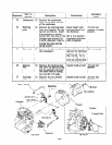
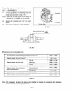
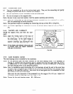
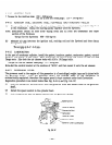
9-4-4 TAPPETS AND CAMSHAFT
Install the tappets first, and then the cam-
shaft.
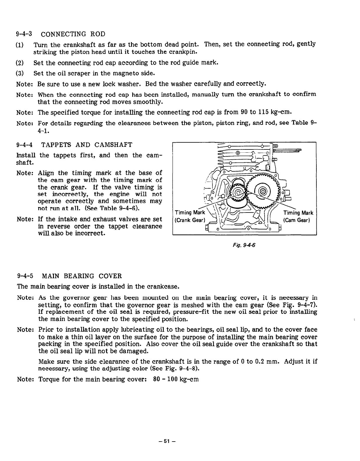
Note: Align the timing mark at the base of
the cam gear with the timing mark of
the crank gear.
If the valve timing is
set incorrectly,
the engine will not
operate correctly and sometimes may
not run at all. (See Table 9-4-6).
Note: If the intake and exhaust valves are set
in reverse order the tappet clearance
will also be incorrect.
~g?zq$==
\
{
,:5g*y
+-J-&[@ f@
Rd q
;:;; :eyr$&p&+&&
gm4;;
L
n
I
Fig. 94-6
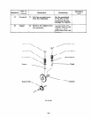
9-4-5 MAIN BEARING COVER
The main bearing cover is installed in the crankcase.
Note: As the governor gear has been mounted on the main bearing cover, it is necessary in
setting, to confirm that the governor gear is meshed with the cam gear (See Fig. 9-4-7).
If replacement of the oil seal is required, pressure-fit the new oil seal prior to installing
the main bearing cover to the specified position.
Note: Prior to installation apply lubricating oil to the bearings, oil seal lip, and to the cover face
to make a thin oil layer on the surface for the purpose of installing the main bearing cover
packing in the specified position.
Also cover the oil seal guide over the crankshaft so that
the oil seal lip will not be damaged.
Make sure the side clearance of the crankshaft is in the range of 0 to 0.2 mm. Adjust it if
necessary, using the adjusting color (See Fig. 9-4-8).
Note: Torque for the main bearing cover:
80 - 100 kg-cm
-51-