5.
DESCRIPTION OF MAIN OPERATIONS
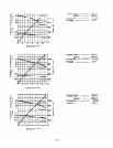
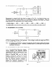
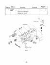
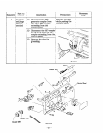
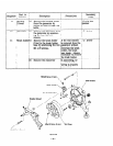
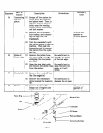
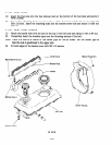
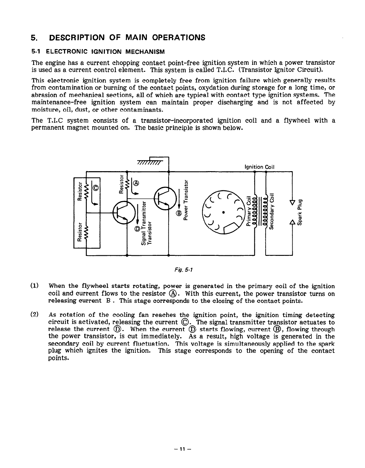
5-l ELECTRONIC IGNITION MECHANISM
The engine has a current chopping contact point-free ignition system in which a power transistor
is used as a current control element. This system is called T.I.C. (Transistor Ignitor Circuit).
This electronic ignition system is completely free from ignition failure which generally results
from contamination or burning of the contact points, oxydation during storage for a long time, or
abrasion of mechanical sections, all of which are typical with contact type ignition systems. The
maintenance-free ignition system can maintain proper discharging and is not affected by
moisture, oil, dust, or other contaminants.
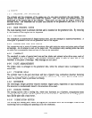
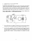
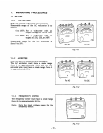
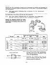
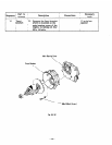
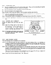
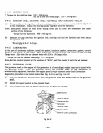
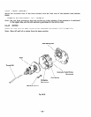
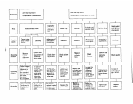
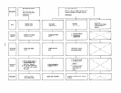
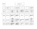
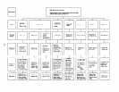
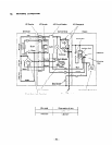
The T.1.C system consists of a transistor-incorporated ignition coil and a flywheel with a
permanent magnet mounted on. The basic principle is shown below.
I
Ignition Coil
I
E @
r
*go .$
$1 r
‘1 Q
b
z
.-
E
P
=
LT
\s>l
f
Ll
f
‘CC = 8
r 8
I
z
.-
E
? ~~~
@5
,” l ?“f $
5
2
;
o$j
5
I%
ki
f%
rn
&F
iTI-
F&. 5-7
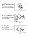
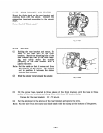
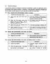
(1) When the flywheel starts rotating, power is generated in the primary coil of the ignition
coil and current flows to the resistor @. With this current? the power transistor turns on
releasing current B .
This stage corresponds to the closing of the contact points.
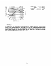
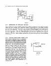
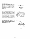
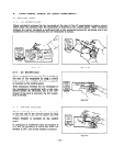
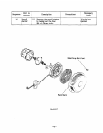
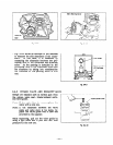
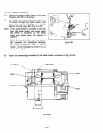
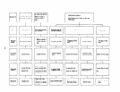
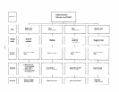
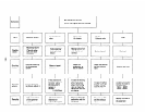
(2) As rotation of the cooling fan reaches the ignition point, the ignition timing detecting
circuit is activated, releasing the current 0. The signal transmitter transistor actuates to
release the current @.
When the current @ starts flowing, current @, flowing through
the power transistor, is cut immediately.
As a result, high voltage is generated in the
secondary coil by current fluctuation.
This voltage is simultaneously applied to the spark
plug which ignites the ignition.
This stage corresponds to the opening of the contact
points.
-11-