


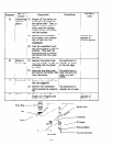
9-4-10 IGNITION PLUG
* Torque for the ignition plug: 230 ad 250 kg-cm
(As for a new one (head plug):
120 s 150 kg-cm)
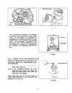
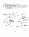
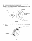
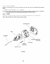
9-4-11 IGNITION COIL, EXCITING COIL, FLYWHEEL AND STARTING PULLEY
(a)
Temporarily set the ignition coil and exciting coil in the crankcase and install the flywheel
in the crankshaft. Clamp the starting pulley together with the flywheel.
Note: Installment should be done after wiping away any oil from the crankshaft and taper
section of the flywheel.
Torque for the flywheel:
600 Q 650 kg-cm
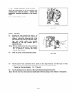
(b)
Measure air gap between the ignition coil, exciting coil and the flywheel and then clamp
the ignition coil.
The air gap is 0.4 s 0.5 mm.
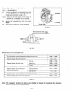
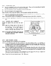
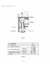
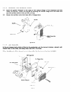
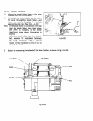
9-4-l 2 CARBURETOR
In the part of crankcase cylinder, install the gasket, insulator, gasket, carburetor, gasket, control
bracket, and gasket, in this order.
Then install the air cleaner body and secure it with two M6
flange nuts. Also lock the air cleaner body with Ml6 x 10 flange bolts.
Torque for the air cleaner clamping:
70 Q 90 kg-cm
Note:Set the control bracket at the position of “RUN”, and then mount it onto the air cleaner.
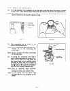
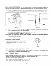
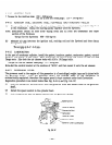
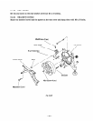
9-4-13 GOVERNOR LEVER
The governor used in the engine
of
this generator is
of
centrifugal weight type and is joined with
the governor lever.
With the governor lever,
the throttle valve
of
the carburetor is
automatically regulated, therefore the engine speed is kept constant under load fluctuation.
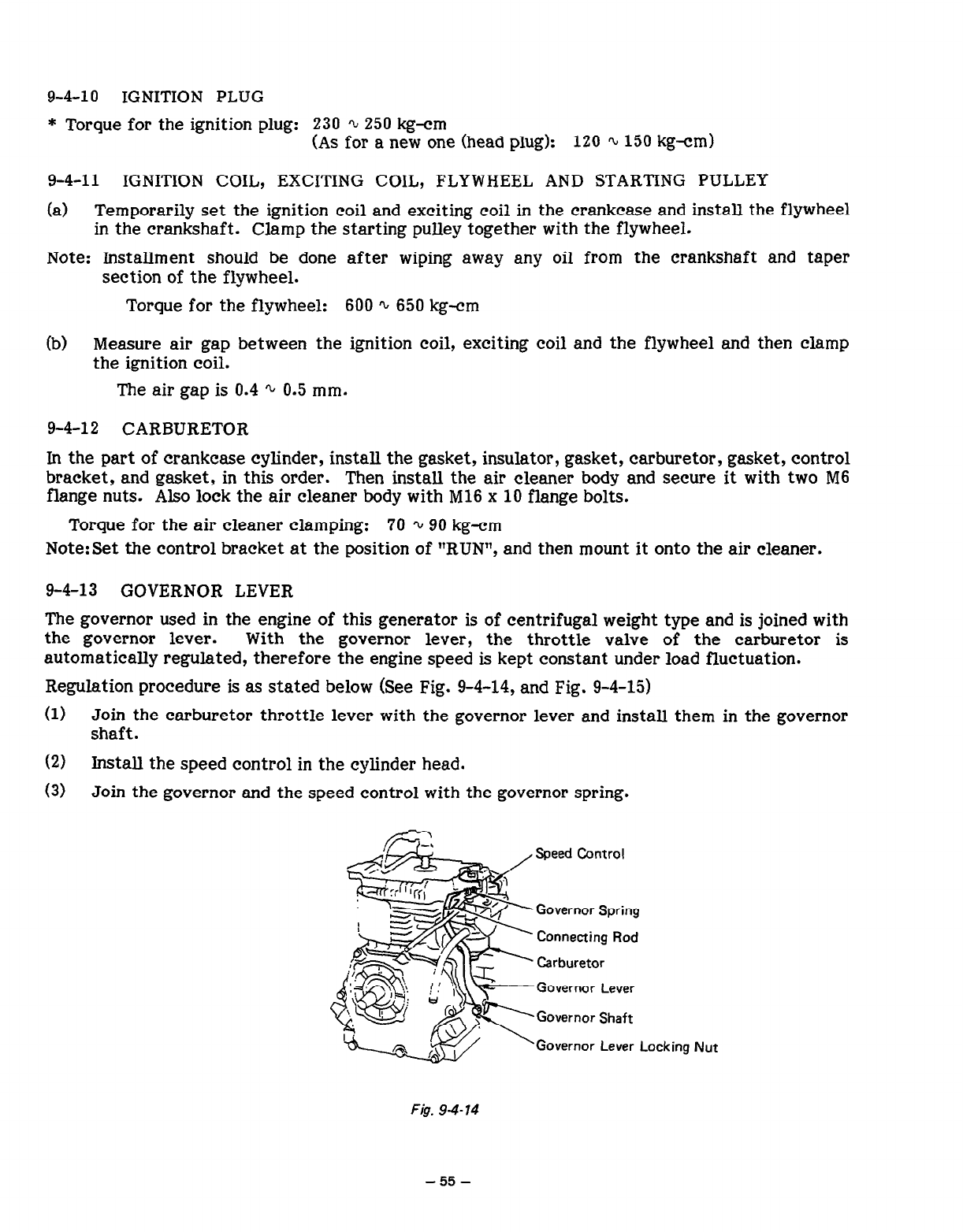
Regulation procedure is as stated below (See Fig. 9-4-14, and Fig. 9-4-15)
(1)
Join the carburetor throttle lever with the governor lever and install them in the governor
shaft.
(2)
Install the speed control in the cylinder head.
(3)
Join the governor and the speed control with the governor spring.
,
a@==-
,,
//
SE+
yl I Ir;; L
- /-!
!zsc-
@
2s
j&f
-&
cc=+
$T, +,
&
\.T< I’
G
‘L--
Governor Lever
Governor Lever
Locking
Nut
F&. 9-4-14
-55-