


Troubleshooting and Maintenance 5‐3MN2408
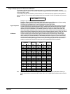
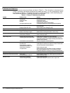
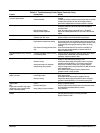
Table 5‐2 Troubleshooting Guide (Digital Controller Only)
Problem Possible Cause Remedy
Controller does not power up even with
correct DC power applied
Wiring Mistake
Overload Condition
Check that there are no wiring errors/short circuits connected to the
controller.
The MEC 20 contains an electronic fuse that trips when an overload
condition exists and does not reset until the supply voltage is
removed and reapplied after the overload condition is corrected.
LCD Display cannot be viewed Microprocessor failure
Improper Supply Voltage
Improper contrast adjustment
Check that the controller's microprocessor is running by observing a
red flashing “watchdog” LED on the rear of the PCB. Replace
controller if failed.
Check DC supply voltage at terminals B+ & B- (10-30VDC).
Adjust LCD contrast potentiometer (R115) on rear of PCB for best
display.
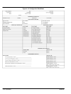
Controller cannot be “Reset” Engine not stopped
Controller not in OFF mode
Verify the engine is at a complete stop before trying to reset.
Set the controller to the OFF mode before trying to reset.
No “RUN” output signal “Shutdown Faults” not reset
Engine speed not detected at cranking
Run Contact not closing (terminals #18 &
#19)
All shutdown faults must be reset (red shutdown LED must be off).
Engine speed signal must be detected (speed signal green LED on)
during cranking if the “run-output fail safe” feature is enabled. Verify
correct magnetic pickup signal at cranking (2.0VAC min. during
cranking).
Check that the RUN output LED (on the rear of the PCB) is on.
If yes, verify relay contact operation on terminals #18 & #19.
Replace controller if failed.
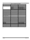
Overspeed shutdown occurs at normal
speed
Controller programmed values are wrong
or controller has failed.
Verify the controller programmed values are correct for the number
of flywheel teeth, nominal RPM, and overspeed setpoint
percentage. Replace controller if failed.
Voltage or current metering is incorrect Controller programmed values are wrong
Ground is missing
Analog input needs to be calibrated
Voltage sensing wiring mistake
Verify the controller programmed values are correct for the voltage
sensing PT ratio and/or current sensing CT ratio.
Verify that the battery supply DC negative conductor is properly
grounded to the engine block (i.e. to a common ground point).
Verify that the controller's analog input is properly calibrated.
Verify the voltage sensing wiring connection to the MEC 20 matches
power distribution type.
Note: standard direct voltage connection requires that the
generators neutral is solidly grounded.
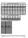
Engine temperature or oil pressure
display is incorrect
Analog input needs to be calibrated
Failed engine sensor
Ground is missing
Verify that the controller's analog input is properly calibrated.
Verify engine sensors.
Note: engine sensors must be factory supplied units only.
Verify that the battery supply DC negative conductor is properly
grounded to the engine block (i.e. to a common ground point).
Engine temperature or oil pressure
displays 9999
OR
Engine alarms are ON for high engine
temperature or low oil pressure when
engine is operating properly
Sending unit is disconnected (open
circuit)
Defective sending unit
Wrong Temp or pressure calibration
Verify the sending units wiring to controller terminals #37 & #38 (i.e.
wiring is not open or shorted).
Verify the engine mounted senders have correct resistance values
for corresponding input temperature or pressure.
Verify calibration.
Keypad Buttons (switches) do not
operate.
Keypad not connected to controller Verify the interconnecting ribbon cable between the lexan faceplate
and main printed circuit board is correctly connected.
Replace controller if failed.