


3‐10 Receiving & Installation MN2408
Transfer Switch Considerations
The following are general considerations for the safe use of a transfer switch:
1. The transfer switch should be located inside the building near the main breaker box or
the disconnect box.
2. The transfer switch must be kept away from any location that might allow water to get
on it.
3. If the transfer switch is mounted outside, it must be protected from the environment and
it's elements.
4. Do not mount the transfer switch on the generator set.
5. Do not mount the transfer switch where flammable liquids or vapors are present.
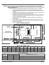
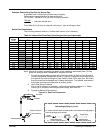
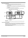
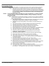
Figure 3‐4 Basic Power Transfer System
Utility Power
Generator Power
L1 L2 N
Main Panel
Fuses or
Circuit
Breakers
Transfer
Switch
Mechanical
Interlock
L1 L2 N
Fuses or
Circuit
Breakers
Power To Load
L1 L2 N
Remote Start
Contact
Earth
Ground
Ground
Ground
Remote Start
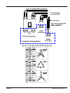
Connect the remote start start contact (from transfer switch) to GLC Remote Start terminals.
Single Phase Power Connections
Output power connections must be fused within 25 feet of the generator. If the wires to the
transfer switch are shorter than 25 feet, connect L1, L2 and N to the transfer switch being sure to
follow NEC and local codes. If the wires to the transfer switch are longer than 25 feet, UL
requires that branch circuit protection be provided.
Power connections are made at L1, L2, Neutral and Ground points indicated in the Customer
Connections area shown in Figure 3‐5.