


4‐26 Operation MN2408
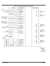
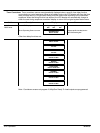
Main Menu Loop
Continued
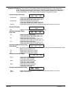
Loss Of Speed Signal Select the desired action (i.e. alarm or shutdown) when a loss of speed signal is detected during operation.
Note: A loss of speed signal must be detected for longer than 2 seconds to initiate the desired action.
Common Fail For “Not In Auto” Function Selects if a common fail alarm condition is to be activated during manual operation.
Horn For Not In Auto The Horn may be programmed to sound when the controllers operating mode is switched from the Auto position. If the
Horn is not to sound, select program setting No.
Warm-up Delay The WARM-UP Delay menu appears when the Gen Ready To Load programmable output is selected (typically for AMF
application). Set to the desired time in seconds, which the generator requires to effectively “warm-up” before accepting
load. This is typically set for 3 seconds. The Warm-Up Delay is initiated after the generator is above programmed voltage
and frequency limits (per the analog programming menus).
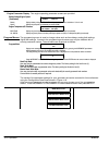
Neutral Delay The Neutral Delay menu appears when the Utility Ready To Load programmable output is selected (typically for AMF
application). The Neutral Delay timer is used when transferring between the available power sources. When transferring
from the utility supply to the generator supply, the Neutral Delay timer will start when the Utility Ready To Load output
de-energizes. When the Neutral Delay time period expires, the Generator Ready To Load output is energized. The
purpose of the Neutral Delay timer is to prevent out of phase transfers, which may be caused by a fast transfer and the
two sources of supply are out of synchronism. The Neutral Delay timer ensures the load voltages decay before the
transfer is initiated. Set to the desired time in seconds. The Neutral Delay timer is typically set for 3 seconds.
Note: The Neutral Delay feature is only effective when an electrically held “contactor-type” transfer switch is connected.
Contact Baldor for further application information on use with other types of transfer switch mechanisms.
Return Delay The Return Delay menu appears when the Utility Ready To Load output is selected (typically for AMF application). The
Return Delay is initiated when the remote start signal is removed (signaling utility power is available). After the Return
Delay timer expires, the Generator Ready To Load output is removed, and the Utility Ready To Load output energizes to
signal transfer the load back to the utility supply. The purpose of the Return Delay timer is to ensure that the utility power
has returned to a steady state for the selected time period before the load is transferred back to the utility supply. The
Return Delay timer is typically set for 120 seconds.
Caution: The Programmable Output Contacts selection must agree with the external control wiring
prior to energizing the controller. Failure to do so may cause severe equipment damage.
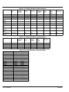
Programmable Output Contacts Select the desired function that will activate the programmable relay output contact.
One of the following functions may be selected:
Energize To Stop Gen Ready To Load Air Flap Eps Supplying Load Utility Ready To Load
Oil Bypass Timer Complete Common Fail Digital Faults #1 to4 Switch Not In Auto
Overspeed Engine Ready Loss Of Speed Signal Engine Run (Fuel)
Low Bat Voltage Preheat High Bat Voltage Engine Running Weak Bat Voltage
ATS Test Low Oil Press #1 Alarm Common Alarm Common Shutdown
Low Oil Press #2 Shutdown High Eng Temp #1 Alarm High Eng Temp #1 Shutdown
Reset Run Hours The hourmeter may be reset to zero hours when yes is programmed.
Note: This programming prompt is only accessible while using the “Master” programming security password.
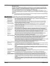
Analog Fault Menu Loop The controller's analog fault settings are described as follows:
Level Sets the actual analog signal setpoint at which the selected fault type will be activated.
Note: For AC voltage fault circuits, two levels (i.e. pick-up & drop-out) must be programmed.
Action Allows a fault to be either an Alarm fault or a Shutdown fault.
Alarm Latch If an fault was set as an Alarm, it may be selected as a “Latching” alarm or “Non-latching” alarm. A Latching alarm is not
cleared until a reset command clears it.
Note: This value only appears if alarm faults are programmed. Shutdown faults are automatically set as latching.
Bypass On Start Delay Allows the alarm or shutdown fault to be disabled until after the bypass timer has expired. Faults that are not delayed are
enabled at all times (i.e. engine running or stopped).
Transient Delay Times Allows the selected fault to be disabled until the delay period has expired. Delay times are 0.0 to 999.9 seconds.