


Operation 4‐25MN2408
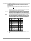
Navigation Hints
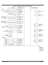
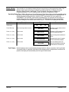
Programming parameters are displayed in the same order as the Programming Sheets (see
Figures 4‐17 to 4‐20). To skip over parameters that do not require changes, push and hold the
ENTER push-button until the desired parameter is displayed. The EXIT push-button may be
used to scroll backwards through the programming parameter loops.
To change a parameter value, use the INCREMENT or DECREMENT push-buttons to scroll
through the available options or to adjust a value as desired and press the ENTER to accept the
new value.
Note: If programming mode is terminated before the last change is accepted (pressing ENTER),
that parameter value will remain unchanged.
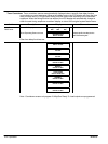
Main Menu Loop The Main Menu Loop contains general system configuration programming such as system input
voltages, currents, transformer ratios, as well as standard operating time delay functions.
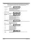
System Voltage Set to nominal system voltage as expressed in phase to phase voltage (i.e. a 347/600 volt system would be entered as
600). The programmable range of values is 120V-15,000V.
System Frequency Set to nominal system frequency of either 50 HZ or 60 HZ.
System Phases Set to match the power distribution system used on the generator set (i.e. either single phase or 3 phase system).
Neutral Connected Set to Yes if generator's neutral conductor is connected to controller terminal TB1-VN and it is desired to display
line-neutral AC voltages for a 3 phase, 4 wire system.
Voltage Sensing Ratio For direct voltage sensing wiring connections from 208 to 600 volts, enter 1 (i.e. a ratio of 1:1). When potential
transformers are utilized for voltage sensing, enter the calculated transformer ratio (e.g. when using 600:120
transformers, enter a number of 5).
Current Sensing Ratio For current sensing wiring connections from current transformers (CT's), enter the calculated CT ratio (e.g. when using a
600:5 CT, enter a number of 120).
Temperature Scale Select the desired units for engine temperature display and analog setpoints: Degrees Fahrenheit or Degrees Celsius.
Note: Alarm setpoints do not automatically re-configure when changing between Fahrenheit or degrees Celsius.
Pressure Scale Select the desired units for engine pressure display and analog setpoints: Pounds per square inch (PSI) or Kilopascals
(KPA). Note: Alarm setpoints do not automatically re-configure when changing between PSI and KPA.
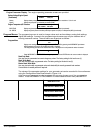
Start Delay Select desired engine start delay time in seconds. If engine start delay is not required, set to zero. Note: If preheat and
or prelube functions are used, the engine start delay time should be set as required for these functions.
Crank Time Select desired cranking time in seconds. If cycle cranking is selected, this time will be the crank time per attempt.
Rest Time Select desired rest time between cranking attempts. (Only valid if multiple crank attempts are selected).
Note: This value will be ignored if only one attempt has been programmed.
Starter Re-Engage Duration This feature checks for a speed signal during cranking. If no speed signal is sensed, the controller assumes that the
engine starter is not turning the engine over and disengages it after the programmed time delay, and re-engages it
again. This process will repeat until a speed signal is sensed or cranking time expires, whichever occurs first.
If a speed signal is sensed, cranking continues until the engine starts or an overcrank condition occurs.
Set time in seconds as desired (i.e. a setting of 5 seconds will attempt cranking for 5 seconds after which time if no speed
signal is detected, the crank output will be removed for a preset 1 second delay before re-engaging.)
Note: This action is more than a cycle cranking function and is independent of the number of attempts selected.
Therefore, the “crank” time should be considered. To disable this feature, set to zero.
Number Of Crank Cycles Set to the number of cranking cycles required. (Zero will default to one.)
Bypass Delay This setting is the time period that Alarm or Shutdown faults will be ignored after crank disconnect, allowing the engine to
settle into its normal operating mode (i.e. proper oil pressure, etc.). Typically 10 seconds.
Cool down Time Set to desired cool down time in seconds. Up to 9999 seconds of cool down time may be programmed. Set to zero if not
required.
Note: If the controller is used in an AMF application it is recommended to set the cool down timer to a minimum of 10
seconds to allow the generator to transfer Off Load before enabling the cool down time. (Ensures the load is transferred
off of generator prior to stopping the engine.)
Nominal Engine RPM Set to the nominal engine speed in revolutions per minute (RPM).
Flywheel Teeth Set to the number of ring gear teeth on the engine flywheel. The magnetic pick-up must be installed to sense the same
teeth for speed sensing as programmed.
Crank Disconnect Speed Set crank disconnect speed in percentage of nominal speed, i.e. 30% or 540 RPM on an 1800 RPM engine.
Overspeed Set overspeed shutdown point in percentage of nominal speed (i.e. 110% or 1980 RPM on an 1800 RPM engine).
Overspeed Transient Delay Select desired overspeed transient delay time in seconds. Time setting may be entered in tenths of seconds.
Run Output Fail-safe When enabled (factory setting), this feature inhibits the run output until the controller receives a speed sensing signal.
This prevents possible damage caused by starting the engine with no speed sensing for crank disconnect and
overspeed. If selected, ensure that the speed signal is not less than 3.0VAC from the magnetic pick up while the engine
is cranking.
Note: If this feature is disabled, no overspeed protection or crank disconnect will be provided if the speed signal fails. If
you disable this feature Baldor strongly recommends that backup crank disconnect protection and additional overspeed
protection is provided.