


General Information 2‐9MN2408
Exhaust System
Exhaust Checklist
A. Exhaust outlets are not located upwind or near any building air intakes.
B. Flexible piping section is used at engine exhaust outlet.
C. Exhaust piping material is adequate for expected service.
D. Exhaust piping sizing is adequate to prevent back pressure.
E. Exhaust piping components are insulated as necessary to prevent operator burns and reduce
pipe radiant heat losses.
F. Pipe sleeves or fire proof materials are used where exhaust pipe passes through building
materials as per local and state codes.
G. Exhaust pipe includes rain cap or is horizontal.
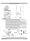
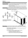
The purpose of the exhaust system is to safely discharge the engine combustion products into
the atmosphere outside the building. A silencer should be installed in the exhaust system to
reduce noise levels. Compliance with local noise codes is always required.
Level Of Attenuation
In general, manufacturers offer three grades of silencers: industrial, residential, and critical. In
most cases, these grades are comparable from make to make. However, attenuation curves for
the silencer should be checked to assure the desired level of silencing is met.
System Placement
By this time, the general genset placement within the room or building has been decided. The
routing of the exhaust system should be as direct as possible to the building exterior.
WARNING: Never allow the exhaust outlet to be positioned so that the exhaust gases are directed
towards any openings or air entry routes (doors, windows, vents, etc...) of an occupied
building. When discharging the hot exhaust gases out of the building do not direct them
towards anything that could catch fire or explode.
For aesthetic reasons, consider exhaust placement in relation to the building. Over a period of
time, exhaust gas carbon deposits will tend to accumulate on any nearby wall or structure.
Attention must also be given to exhaust noise in selecting placement of the exhaust system.
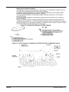
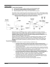
Multi-Engine Installations
Caution: Do not connect multi-engine exhaust systems together. Each engine must have its own
exhaust system for proper operation.
Exhaust gases from an operating engine will migrate back through a non-operating engine and
cause a hydraulic lock. This may interfere with starting of the second engine. The migrating
gases will also tend to turn the turbos which are not being provided lubrication if the engine is not
running. The use of check valves in the exhaust system are discouraged due to their tendency
to “stick”.
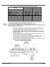
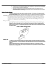
Exhaust Manifold
There are two exhaust manifold types. Dry type which is standard and the optional water cooled.
The dry type is simply exposed to the surrounding air and becomes very hot. Shields, insulating
wraps, or other types of guards can be used to limit operator contact with the hot surfaces. This
practice is common where engine room size is small, creating cramped conditions.
Water cooled exhaust manifolds are not available on all engine models. This type manifold has
passages through which engine coolant is circulated to remove heat from the manifold surface. It
also will help protect the operator from contact with the hot manifold surface. This will reduce the
amount of heat that is radiated by the engine to the surrounding air by approximately 20%. In
addition, this type manifold significantly increases the amount of heat the cooling system must
dissipate. Marine and Mining Safety Administration (MSA) codes may require water cooled
manifolds in all genset installations. If you are in doubt on your particular application, consult your
Baldor Distributor.
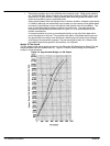
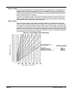
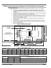
Exhaust Gas Restriction
The maximum allowable back pressure, or system restriction, is 3 inches of mercury. If this back
pressure is exceeded, the air-fuel ratio is reduced due to incomplete scavenging of the cylinders,
fuel economy and power output is reduced, engine life is reduced and exhaust temperatures and
smoke levels increase. Any restriction of the exhaust gas reduces horsepower. Take every
precaution to reduce restriction. Proper design and installation will provide safe genset operation.
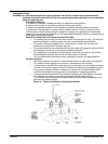
It is essential that all engine exhaust systems by designed with the least possible restriction to
exhaust gas flow. This can be calculated through the use of Figure 2‐6, or in the case of simple
exhaust systems, the nomograph in Figure 2‐6 may be used.