


Operation 4‐13MN2408
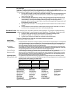
Operator Control Panel (MICROPROCESSOR Engine Controller Only)
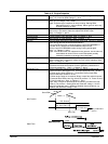
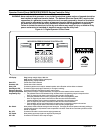
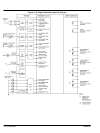
The Operator Control Panel is shown in Figure 4‐13.
WARNING: Never connect this generator to any buildings electrical system unless a licensed electrician
has installed an approved transfer switch. The National Electrical Code (NEC) requires that
connection of a generator to any electrical circuit normally powered by means of an electric
utility must be connected by means of approved transfer switch equipment so as to isolate
the electrical circuit from the utility distribution system when the generator is operating.
Failure to isolate the electrical circuits by such means may result in injury or death to utility
power workers due to backfeed of electrical energy onto the utility lines.
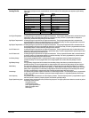
Figure 4‐13 Digital Operator Control Panel
DECREMENT
SILENCE RESET
SHUTDOWN
ALARM READY
SPEED SIGNAL
EMERGENCY
STOP
RUN OFF AUTO
LOAD
TEST
EXIT ENTER
LAMP TEST
MICROPROCESSOR ENGINE CONTROLLER
INCREMENT
Vavg
000
Aavg
000
Freq
000
VOLTAGE
ADJUST
-+
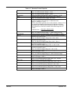
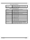
LCD Display - Vavg (average voltage) display 0-999 volts.
Aavg (average amperage) display 0-999 amperes.
Freq (frequency) display 0-999 hertz.
Alarm LED- Flashes when a fault is detected.
Shutdown LED- Flashes when a fault is detected.
Ready LED- On when the generator set is ready for automatic operation and no Shutdown or Alarm faults are detected.
Speed Signal LED- On when the engine speed signal is detected (i.e. the engine is cranking).
Emergency Stop LED- On when the Emergency Stop Switch is used to stop the engine.
Emergency Stop Switch- When pushed, the engine is stopped immediately. The engine cannot be restarted until the controller is reset.
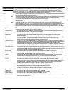
Programming Keys Exit pushbutton used to scroll backward through the status menus or programming prompts to the previous item.
Note: The longer the push-button is held down, the faster the menu prompts appear.
Decrement pushbutton used to reduce a programming value while in the programming mode.
Note: The longer the push-button is held down, the faster the value will be decremented.
Increase pushbutton used to increase a programming value while in the programming mode.
Note: The longer the push-button is held down, the faster the value will be incremented.
Enter pushbutton used to scroll forward through the status menus or programming prompts to the next item.
Note: The longer the push-button is held down, the faster the menu prompts appear.
Run Switch- When pushed, initiates a manual start signal to start the engine. The engine will start and operate continuously providing no
shutdown faults are active. All protective circuits are operative in this mode. There will be no cool down cycle at the end of a
manual run sequence.
Run LED- On when the Run switch is used to start the engine (generator set).
OFF Switch- When pushed, sends a stop signal to the engine to stop the engine.
OFF LED- On when the OFF Switch is used to stop the engine.