


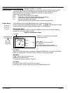

4‐10 Operation MN2408
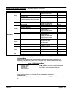
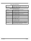
Table 4‐18 Sensor Spec Setpoints
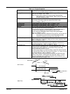
Calibr AI1,AI2, AI3 Calibrating constant to adjust the measured value of IL analog inputs.
Physical dimension of calibrating constant is corresponding to Analog
input. Step: 1; Range: -1000 to +1000
AnOut-kW/20mA Conversion coefficient from gen-set power to iG-IOM or PTM analog
output. Step: 1; Range: 1 to 32000
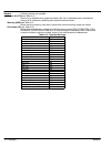
Table 4‐19 IOM/PTM Module Setpoints
AnlInIOM1 lev1 The level for IOM ANALOG INPUT 1 alarm detection.
Step: 1; Range: -100 to +10000
AnlInIOM1 lev2 The level for IOM ANALOG INPUT 1 alarm detection.
Step: 1; Range: -100 to+10000
AnlInIOM1 del Delay for IOM ANALOG INPUT 1 alarm. Step: 1 s; Range: 0 - 180 s
AnlInIOM2 lev1 The level for IOM ANALOG INPUT 2 alarm detection.
Step: 1; Range: -100 to +10000
AnlInIOM2 lev2 The level for IOM ANALOG INPUT 2 alarm detection.
Step: 1; Range: -100 to +10000
AnlInIOM2 del Delay for IOM ANALOG INPUT 2 alarm. Step: 1 s; Range: 0 - 180 s
AnlInIOM3 lev1 The level for IOM ANALOG INPUT 3 alarm detection.
Step: 1; Range: -100 to +10000
AnlInIOM3 lev2 The level for IOM ANALOG INPUT 3 alarm detection.
Step: 1; Range: -100 to +10000
AnlInIOM3 del Delay for IOM ANALOG INPUT 3 alarm.
Step: 1 s; Range: 0 - 180 s
AnlInIOM4 lev1 The level for IOM ANALOG INPUT 4 alarm detection.
Step: 1; Range: -100 to +10000
AnlInIOM4 lev2 The level for IOM ANALOG INPUT 4 alarm detection.
Step: 1; Range: -100 to +10000
AnlInIOM4 del Delay for IOM ANALOG INPUT 4 alarm. Step: 1 s; Range: 0 - 180 s
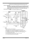
The protection of IOM/PTM inputs is activated by over crossing the limits.
Calibr AInIOM 1..4 Calibrating constant to adjust the measured value of IOM/PTM analog
inputs. Physical dimension of calibrating constant is corresponding to
Analog input. Step: 1; Range: -1000 to +1000