


General Information 2‐11MN2408
Transfer Switch
Transfer Switch Checklist
A. Locate transfer switch in a clean, dry place, near the emergency load.
B. Provide a circuit breaker between the genset and the transfer switch.
C. Put a flexible connection between the conduit and genset.
D. Observe applicable codes in wiring-in the transfer switch and genset.
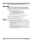
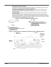
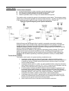
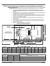
The transfer switch connects the genset to the emergency power system. The emergency power
system may include several gensets and several transfer switches. Typically, the genset is wired
to the emergency power system through a transfer switch as shown in Figure 2‐8.
Figure 2‐8 Typical Emergency power System Installations
Multiple Gensets can be arranged either in parallel or separately connected to dedicated
emergency loads. Figure 2‐8 also shows a typical arrangement of two gensets in parallel with
transfer switches for loads that have different levels of priority. A typical multiple genset
installation is shown for NFPA 110 Level 1 and Level 2 emergency power circuits and a priority
control to select the appropriate transfer switch.
Wattmeters should be installed on each genset so load sharing can be checked. The control
system should include an automatic paralleling control. Paralleling identical gensets is not
difficult, but paralleling dissimilar sets can cause load sharing problems. When designing an
installation that includes the paralleling of dissimilar generators, contact your nearby Baldor
Distributor.
Transfer Switch Location
The transfer switch location is important and key considerations are:
1. Locate the transfer switch as close to the emergency load as practical to avoid
interruptions of the emergency power system due to natural or man-made disasters, or
to equipment failures. Consider several small transfer switches instead of one large
one to increase reliability.
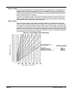
2. Locate the transfer switch in a clean, dry, well ventilated location, away from excessive
heat. When the ambient air is above 104 F (40 C), fuses and circuit breakers must be
derated. Allow adequate working space around the transfer switch.
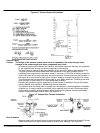
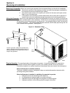
3. A circuit breaker (or fuses) should be installed in the line between the generator and
the transfer switch. Baldor Gensets are available with properly sized circuit breaker
built into the generator control through 1200 amp breakers. The circuit breaker can be
separately mounted. In the case of very large circuit breakers, a separate floor
mounted circuit breaker is easier to wire up than a wall mounted breaker.
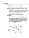
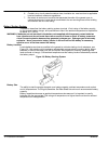
4. Install power and control wires in separate solid conduit with flexible sections at the
genset. The flexible sections prevent vibration from damaging the conduit. All power
conduits from the genset must contain all three phases.
5. Never install control wires in the same conduit as power conductors.