


4‐20 Operation MN2408
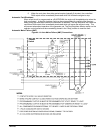
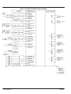
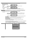
Output Contacts All output contacts are non-powered (i.e. dry contacts) and are rated 10A/240VAC, 8A/28VDC
resistive (3A inductive, 0.4pf). Output contacts are not fused therefore external overcurrent
protection (maximum 10A) is required for all control circuits using these contacts. Contacts are
shown in a de-energized state and will change state upon activation.
Run The Run contact is a Form “A” dry contact to control the engines “Run” circuit. This typically includes external control devices
such as “Fuel Rack Solenoids” or electronic governors.
Note: An additional pilot relay will be required to energize high current devices that exceed the 10A resistive rating. The run output
control logic provides an “Energize To Run Signal“ (i.e. the run contact closes when a run condition is activated).
For energize to stop control logic, refer to the programmable output control function.
Crank The Crank output contact is a Form “A” dry contact and is used to control an external crank pilot relay that directly controls the
engine starter motor.
Note: An external crank pilot relay is required to energize the high current starter motor pinion solenoid that exceeds the 10A
resistive crank output contact rating. The crank output contact closes when a crank condition is activated and the contact will
automatically open when crank disconnect speed is obtained and/or the generators output AC voltage exceeds 10% of
nominal level. The generators output AC voltage is utilized for back-up crank disconnect protection should the speed sensor
fail.
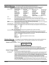
Programmable Contacts Four (4) standard programmable output contacts are provided, #1, #2, #3 and #4. Each programmable output is a Form “C”
dry contact that is programmable for any of the following conditions:
Energize To Stop The output relay will energize when a stop signal has been activated. The output will remain energized for 10 seconds
after the engine has come to a complete stop, then de-energizes.
Switch Not In Auto The output relay will energize when the controller's operation mode switch is not in the auto position.
Engine Ready The output relay will energize when the controller's mode switch is in the auto mode and no shutdown or alarm
conditions are present.
Preheat The output relay will energize during the start delay timer period and cranking period until the engine starts and reaches
crank disconnect speed. The preheat output is typically used for an engine starting aid such as glow plugs.
Note: An external pilot relay is required to switch the high current glow plug load.
GEN Ready To Load The output relay will energize when the generators output voltage and frequency exceeds predetermined setpoints (e.g.
voltage 90% nominal, frequency 95% nominal as user programmed) and a warm-up time delay period expires. After the
output has energized, it will remain on (regardless of voltage/frequency levels) until the controller either has a
stop/shutdown signal, or the engine's speed drops below crank disconnect level. The voltage, frequency and time delay
levels are programmable. This output is typically used in an Auto Mains Failure (AMF) application.
Utility Ready To Load The output relay will energize when the remote start input has not been activated (i.e. contact on terminals 16 & 17 not
closed) and the Return Delay & Neutral Delays have expired (if programmed). The output will de-energize when the
remote start input has been activated and the Engine Start Delay & Warm-Up Delays have expired (if programmed). This
output is typically used for Auto Mains Failure (AMF) applications.
Engine Running The output relay will energize when the engine has started and has reached crank disconnect speed.
Engine Run (Fuel) The output relay will energize when the engine “RUN” (i.e. FUEL) energizes prior to the engine starting. The output will
remain on until the engine has reached a “stop” or “shutdown” command.
Airflap The output relay will energize when the engine's speed exceeds the overspeed setpoint level. The output will remain
energized until the engine's speed drops below the low speed setpoint (typically 5% of rated speed).
Note: An external pilot relay is required if the main air flap solenoid current rating exceeds the contact rating.
ATS Test This feature is only operative if the remote transfer switch is interconnected with remote testing capability.
The output relay will energize when a load test operating mode is selected by the “Load Test” keypad push-button. After
initiated, the engine will receive a start signal from the transfer switch and when the generator reaches nominal voltage
and frequency levels, a load transfer will be initiated. The generator set will remain running on load until a different
operating mode is selected or the generator set develops an alarm or shutdown condition.
Note 1: When the “Utility Ready to Load” and “Generator Ready to Load” outputs are programmed, the “Load Test”
programmable output is not required as the engine starting logic is internally initiated.
Note 2: When both “Utility Ready to Load” and “Generator Ready to Load” outputs are programmed for an AMF control
configuration, the ATS Output is not used (i.e. engine start signal is internally generated).
Oil Bypass Timer Complete The output relay will energize when the controller's oil bypass delay timer expires, following a normal start sequence.
Common Alarm The output relay will energize when any alarm fault has been activated.
Common Fail The output relay will energize when any alarm or shutdown fault has been activated.
Common Shutdown The output relay will energize when any shutdown fault has been activated.
EPS Supplying Load The output relay will energize when the engine is running and the generator is supplying current to the load more than or
equal to 10% of nominal CT ratio.