


Operation 4‐17MN2408
No Load Test
To allow a timed No Load Test of the engine/generator set while using the AMF control
application, a digital input contact from an external timer must be programmed for NO LOAD Test
The sequence of operation for a No Load Test condition is as follows:
1. With the utility supply normal and the generator stopped, a no load test sequence may
be initiated by closing an external exercise timer contact to the programmed digital
input for No Load Test.
2. After the external exercise timer contact closes, the engine will start and come-up to
normal operating speed and voltage. The controller will issue an alarm of a No Load
Test condition. The connected transfer switch will remain on the utility and the
generator will not transfer on load. Note: should the utility supply fail, the generator will
automatically transfer on load.
3. The engine will continue to run as long as the external exercise timer contact remains
closed.
4. After the external exercise timer contact opens, the engine will continue to run for its
cool down time as programmed, then it will automatically stop.
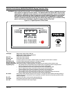
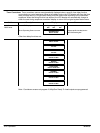
Standard Faults When a fault occurs, information about the fault is displayed. The engine controller has many
analog and digital inputs for monitoring and control operations. Three types of faults are used:
1. Internal Faults are derived from a combination of digital and analog inputs.
2. Digital Input Faults are initiated from external contact inputs.
3. Analog Input Faults are initiated from external analog signal inputs.
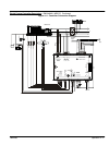
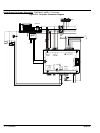
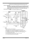
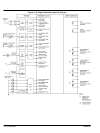
Figure 4‐15 shows how the controller inputs and outputs are organized.
A description of each is provided.
Internal Faults
Overspeed Shutdown Overspeed Shutdown is initiated when the engine's speed has increased above the overspeed setpoint. The overspeed fault
circuit is internally programmed as a latching shutdown fault. The overspeed shutdown fault circuit is programmable for the
percentage of nominal engine speed (i.e. overspeed setpoint) and for the transient time delay period. The programming
prompts for overspeed are located in the main menu programming loop.
Loss of Speed Loss Of Speed is initiated when the engine's speed sensing circuit does not detect a speed signal for a period more than 2
Alarm/Shutdown seconds following a run signal. The loss of speed fault may be user programmed as a latching shutdown fault or alarm only.
The programming prompts for loss of speed are located in the main menu programming loop.
Overcrank Shutdown Overcrank Shutdown is initiated when the engine fails to start after the selected crank time or number of crank cycles. The
overcrank fault circuit is internally programmed as a latching shutdown fault and is not user programmable.
Switch not in AUTO Switch not in AUTO is initiated when the controller's operating mode switch is changed from the auto position to any other
position (ON the keypad). This fault is internally programmed as a non latching alarm. In the main programming loop, this
alarm may be user programmed to initiate the common fail output relay.
Digital Input Faults Four digital faults are provided and these are user programmable. Each digital fault input circuit is activated by a remote
Digital Inputs (N/O or N/C) sensing contact that is external to the controller. Each digital fault input circuit may be programmed with a unique fault label
description as stored in the controller's non-volatile memory.
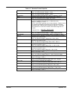
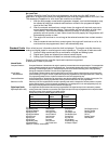
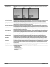
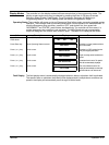
Factory settings have four standard digital faults as follows:
Fault
Name
Fault
Action
Digital Inputs
Terminal #
Low Oil Pressure Shutdown 1
High Engine Temperature Shutdown 2
Battery Charger Input Fail Alarm 3
Low Fuel Level Alarm 4
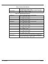
The following is a list of all digital faults:
High Bearing Temp Failed To Sync Reverse Power Bat Charger Input Fail
High Cooler Vibration Low Fuel Press Fail To Sync Bat Chrg Trouble
High Engine Temp Low Engine Temp Vent Damper Fail Bat Charger Fail
High Engine Vibration Low Oil Pressure Gen Breaker Open DC Fail
High Fuel Level Low Fuel Level Ground Fault Breaker Tripped
High Oil Level Low Oil Level No Load Test Basin Rupture
High Oil Temp Fuel Leak ATS In Bypass
High Winding Temp Low Fuel Press Remote Emerg. Stop
*Highintkmanftemp Low Coolant Level Air Damper Tripped
“Blank” (i.e. no text for unused inputs)