


General Information 2‐13MN2408
Battery Charger
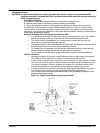
An engine mounted alternator charges the batteries during engine operation. Standby gensets
should include a solid state battery charger that is connected to utility power so the battery is
charged continuously while the genset is not running. The battery charger should be connected
to the utility power emergency circuit. The batteries on prime power gensets are charged by the
engine mounted alternator, if equipped.
The output of the battery charger or the belt driven alternator must be connected directly to the
battery or to the battery terminals on the starter to prevent the electronic governor from acting
erratically. Make control connections to the genset control using a conduit with a flexible section
at the genset to avoid damage due to genset vibrations.
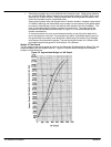
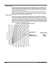
Battery Cables
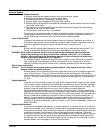
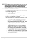
The wire size (wire gauge) of the cables connecting the starter to the batteries must be large
enough to ensure proper voltage at the engine starter motor during cranking. The total cranking
circuit resistance includes the resistance of the cables from the starting motor to the battery and
the resistance of all relays, solenoids, switches, and connections. The resistance of various sizes
of cables is shown in Figure 2‐10. For purposes of calculating cranking circuit resistance to select
cable size, the resistance of each connection can be taken as .00001 ohms and the resistance of
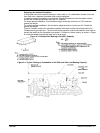
each relay, solenoid, and switch can be taken as .0002 ohms. Figure 2‐10 illustrates an example
of a typical cranking circuit resistance calculation.
Figure 2‐10 Typical Battery Cable Calculations