


Section 4
Operation
Operation 4‐1MN2408
Digital Engine Controller Description EM0046A21 (MRS17)
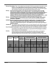
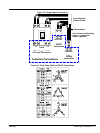
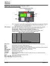
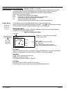
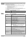
Figure 4‐8 Operator Control Panel
Stop
Manual
Run
Display
Menu
Group
LED Indicators
Operating Modes and
Horn & Fault Reset
Note: The operator control panel is equyipped with a heater element that allows the LCD display
to operate to -40C (not the entire generator set, see generator specifications). This
heater operates from the main battery power.
LED Indicators Alarm (red) - Alarm (shutdown) condition occurred. Annunciates & shuts down generator.
Not In Auto (red) - Control is not in auto mode and cannot provide standby power.
Running (green) - Generator is running, no alarms or warnings.
Warning (yellow) - A warning condition has occurred. Annunciates only.
Ready/Auto (green) - Control is in Auto mode and ready to provide standby power.
Supplying Load (green) - Generator is providing output voltage to load.
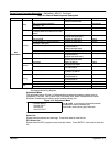
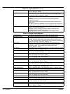
Table 4‐8 Alarm & Warning Conditions
Alarm Warning
X X High Coolant temperature
X X Low Oil pressure
X X Low Fuel level
X X Generator Under/Over Voltage
X X Generator Under/Over Frequency
X X Generator Over Current
X Generator Overspeed
X Coolant temperature Low
X Starting battery Under/Over Voltage
Manual Run Immediately begins the crank cycle to start engine and produce power (MAN mode only).
Start Start generator set operation (MAN mode only).
Stop Stops the Engine and generator set (MAN mode only).
Display Displays setpoints, adjustments, Alarms and Warning conditions and Operating Mode selections.
Page Changes menu displayed - Measurement, Adjustment or History.
Mode A and " Allows selection of OFF - MAN - AUTO mode choices.
Horn Reset Deactivates the Horn output.
Fault Reset Reset Alarms and Warnings.
Y and B Selects the menu choice, select the setpoint or select the menu or increase/decrease the
setpoint value.
Enter Confirm and accept changed setpoint value.
Enter + Y and B Adjusts display contrast.
Enter+ Fault Reset Clears engine ECU faults.