


4‐28 Operation MN2408
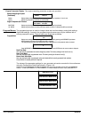
Span Calibration Energize the generator supply voltage to the controller at nominal level. Note: It may be necessary to program the
optional under and over voltage shutdowns as alarms to ensure the generator will continue to operate during calibration.
Caution must be taken to ensure the generator output voltage is set within nominal limits. In the programming mode,
scroll to the desired generator supply voltage phases with the SPAN function selected. Connect an external AC voltmeter
of adequate voltage range and accuracy to the controller terminals associated with the voltage phases to be calibrated.
Use the INCREMENT or DECREMENT push-buttons to adjust the correction factor number while observing the
displayed voltage level. Adjust the correction factor number to obtain an identical voltage reading as measured with the
external AC voltmeter. With the correct voltage displayed, press the ENTER push-button to accept the correction factor
number. Record the correction factor number on the programming sheet for future reference.
Note: When the span calibration setting is complete, re-confirm the zero calibration points. If the zero calibration setpoint needs
further adjustment, the span calibration point must also be re-calibrated.
Current Sensing Calibration To accurately calibrate the current sensors, an external test AC ammeter and current clamp
is required, with an accuracy of 0.5% or better.
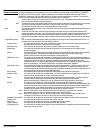
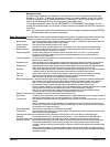
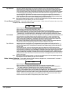
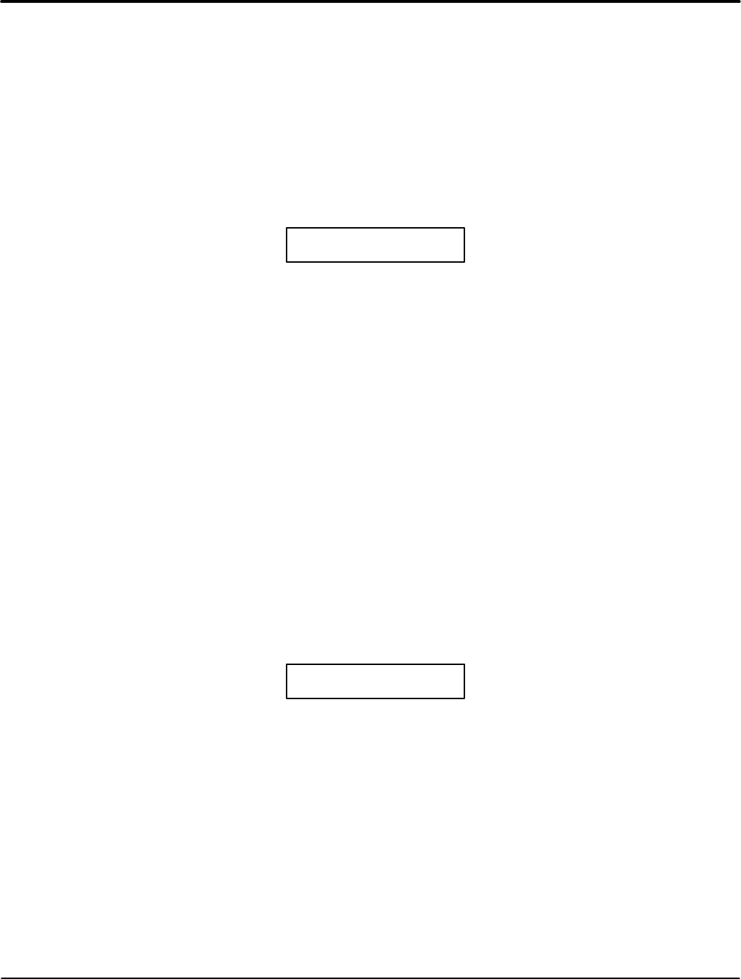
CURRENT A ZERO
99 350A
Displays the generator load current (phase A, B or C) to be calibrated.
Displays the type of calibration function, either ZERO or SPAN.
Displays the calibration correction factor number (0-255) used to obtain the correct current reading.
Note: To correctly calibrate any of the current sensors, the ZERO function must be calibrated before the SPAN function.
Displays the actual current measurement that will be the same value as shown on the MEC 2 display menus for
generator supply. This current reading may be calibrated higher or lower by changing the correction factor number.
Zero Calibration Connect an external AC ammeter with current clamp of adequate current range to the controller terminals associated with
the current phases to be calibrated. With the generator stopped, confirm there is “0” current on the phases to be
calibrated. In the programming mode, scroll to each of the desired generator supply current phases with the ZERO
function selected. Use the INCREMENT or DECREMENT push-buttons to adjust the correction factor number while
observing the displayed current level. Adjust the correction factor until “0” amps is displayed.
With the correct current displayed, press the ENTER push-button to accept the correction factor number. Record the
correction factor number on the programming sheet for future reference. Repeat for each phase.
Span Calibration Apply 50%-100% load to the generator set. It is recommended to load the generator set to 100% rated load for
calibration purposes to obtain good accuracy throughout the full span of operation. Do not exceed the current rating of
the CT. Non-linear output of the CT will result when the secondary current exceeds 5 amps and will similarly effect the
displayed values.
In the programming mode, scroll to the desired generator supply current phases with the SPAN function selected.
Connect an external AC ammeter and current clamp of adequate current range to the controller terminals associated with
the current phases to be calibrated. Use the INCREMENT or DECREMENT push-buttons to adjust the correction factor
number while observing the displayed current value. Adjust the correction factor number to obtain an identical current
reading as measured with the external AC ammeter. With the correct current displayed, press the ENTER push-button to
accept the correction factor number. Record the correction factor number on the programming sheet for future reference.
Repeat for each phase.
Note: When the span calibration setting is complete, re-confirm the zero calibration points. If the zero calibration setpoint needs
further adjustment, the span calibration point must also be re-calibrated.
Battery Voltage Calibration To accurately calibrate the MEC 2 battery voltage sensor, an external test DC voltmeter is
required, with an accuracy of 0.5% or better.
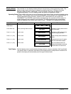
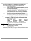
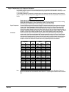
BAT VOLTS SPAN
99 24.6V
Displays the type of calibration function (SPAN).
Displays the calibration correction factor number (0-255) used to obtain the correct voltage reading.
Displays the actual battery voltage measurement that will be the same value as shown on the MEC 2 display menu.
This voltage reading may be calibrated higher or lower by changing the correction factor.
SPAN Calibration Energize the battery supply voltage to the controller and connect the external test DC voltmeter to the battery terminals,
B+ and B-. In the programming mode, scroll to the battery span calibration point. Use the INCREMENT or
DECREMENT push-buttons to adjust the correction factor number while observing the displayed battery voltage level on
the MEC 2. Adjust the correction factor number to obtain an identical voltage reading as measured with the external DC
voltmeter. With the correct voltage displayed, press the ENTER push-button to accept the correction factor number.
Record the correction factor number on the programming sheet for future reference.