Hydraulic Installation 27
PN-46018 (Rev. 3/15/02)
#56038 Valve Kit & #46047 Hose Kit Cont’d
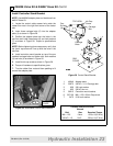
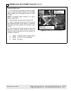
Install IN & PBY Lines
1. If not done during installation of right rear loader
mount, remove the tractor hydraulic line connector
tube or adapter block (if equipped) as shown in Figure
2, Page 7.
NOTE: If 90-degree elbow includes a nut and a
sleeve, discard them.
2. Remove plastic cap from tractor hydraulic line.
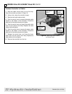
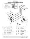
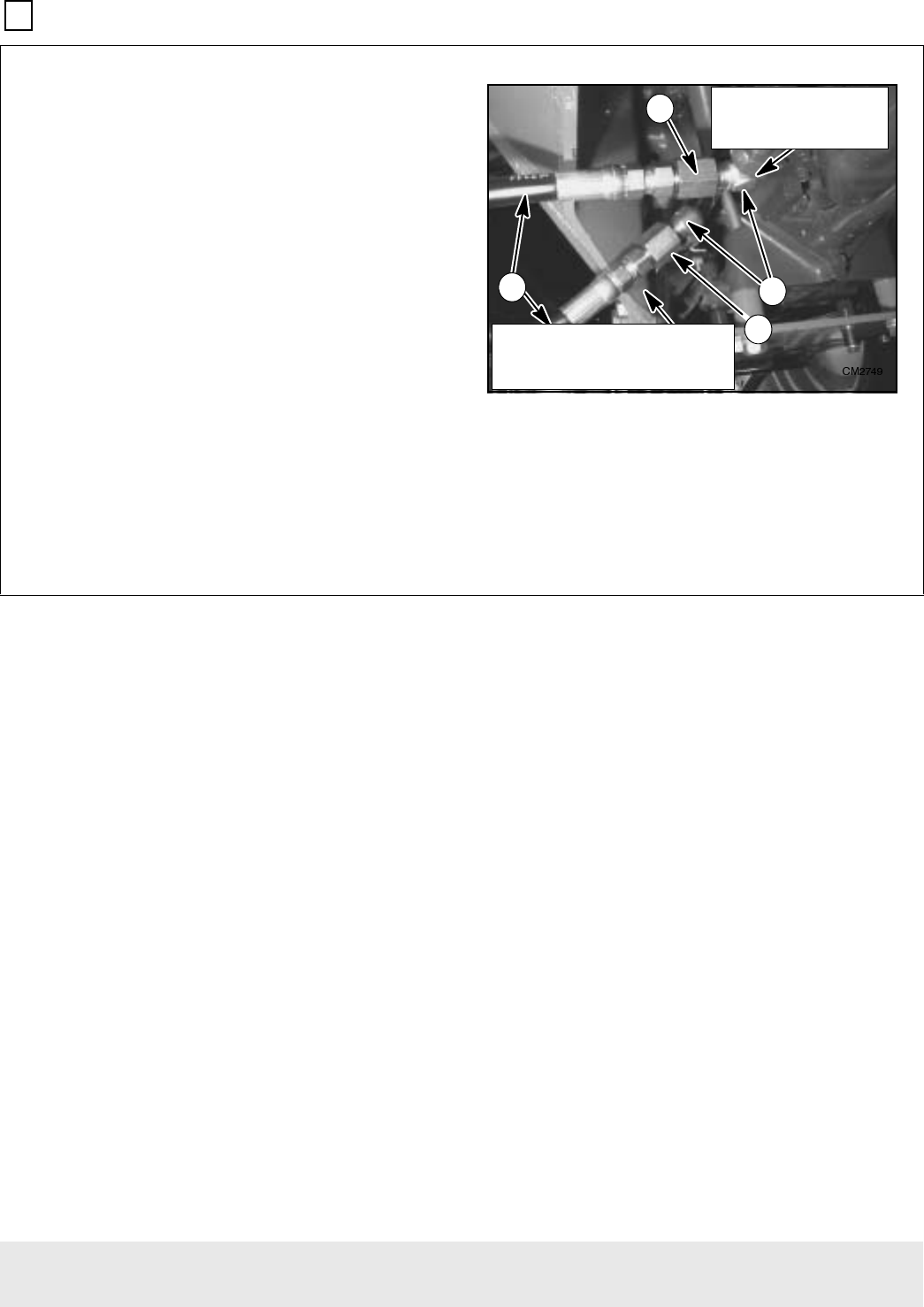
3. Refer to Figure 30. Route hose (3) from valve IN
port outside the loader mount to elbow (1) installed to
the engine end of the hydraulic line as shown in Fig-
ure 32.
4. Refer to Figure 30. Route the hose (3) from valve
PBY port outside the loader mount to elbow (1)
installed in the transmission end of the hydraulic line
as shown in Figure 32.
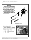
1. 40549 1/2 NPTM x M26 x 1.5M 90° Elbow
2. 315038 1/2 NPTF x 3/4 JICM Adapter
3. 46046 38” Hoses
Figure 32 Tractor PBY & IN Connections
3
)520 /2$'(5 9$/9(
3%< 3257
75$160,66,21 (1'
72 /2$'(5 9$/9(
,1 3257
(1*,1( (1'


