


24 Hydraulic Installation
PN-46018 (Rev. 3/15/02)
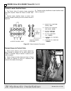
#56038 Valve Kit & #46047 Hose Kit Cont’d
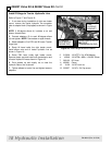
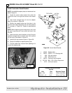
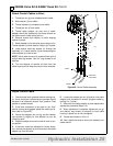
Install Controller Stand
1. Attach controller stand to controller mount
bracket, using four 3/8 x 1-1/4 carriage bolts, 3/8 flat
washers, lock washers, and nuts.
2. Attach controller to controller stand, using three
5/16 x 4-1/2 cap screws, 5/16 lock washers, and nuts.
NOTE: Be sure the handle is positioned with the
“float” position forward (see Figure 35).
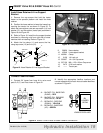
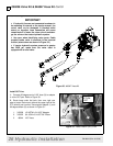
3. Adjust the controller stand, maintaining at least 4”
spacing between the control ever and any restriction
(hand throttle, door, fender, or hydraulic levers).
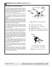
4. Position the controller stand so that the loader
control movements will not be restricted.
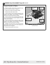
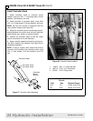
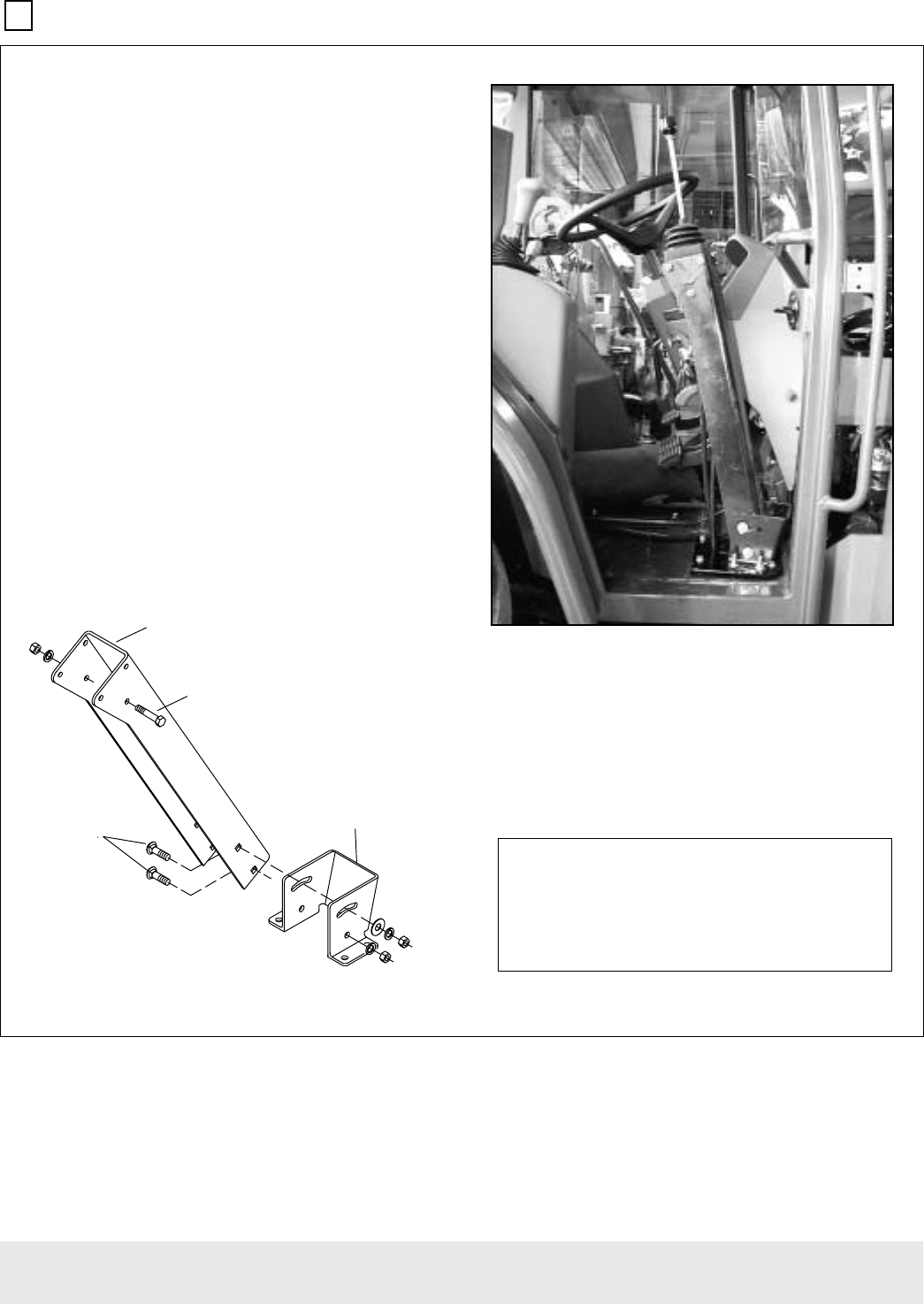
5. Apply controller operational decals to a clean sur-
face that is visible to the operator. See Figure 28 for
completed installation.
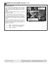
NOTE: If using a 3-spool valve, attach the auxiliary
controller to the outside of the controller stand, using
5/16 x 6 cap screws, 5/16 lock washers, and 5/16
nuts.
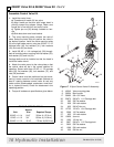
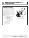
Figure 27 Controller Stand Assembly
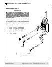
Figure 28 Controller Stand Installed
1. 20973 3/8 x 1-1/4 Carriage bolt
2. 300110 5/16 x 4-1/2 Cap screw
3. 301001 5/16 x 6 Cap screw
3
VSRRO YDOYH
VSRRO YDOYH
&RQWUROOHU 6WDQG
&RQWUROOHU
0RXQW
%UDFNHW
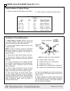
TORQUE SPECIFICATIONS
Wrench
Bolt Size Required Torque
5/16 1/2” 19 lbs.-ft.(26 N-m)
3/8 9/16” 35 lbs.-ft.(47 N-m)