


20 Hydraulic Installation
PN-46018 (Rev. 3/15/02)
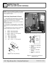
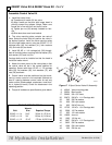
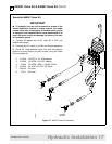
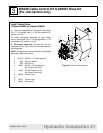
#56037 Valve Kit & #40547 Hose Kit Cont’d
Torque Hardware & Tighten Fittings
1. Torque all hardware to specifications given below.
2. Check to be sure all hydraulic fittings are tight.
2
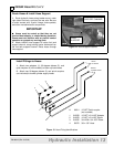
TORQUE SPECIFICATIONS
Wrench
Bolt Qty Size Required Torque
1/4 x 3/4 1 7/16” 10 lbs.-ft.(13 N-m)
5/16 x 3/4 2 1/2” 19 lbs.-ft.(26 N-m)
3/8 x 1-1/2 4 9/16” 35 lbs.-ft. (47 N-m)
1/2 x 1-1/2 2 3/4” 85 lbs.-ft. (115 N-m)
5/8 x 1-1/2 2 15/16” 170 lbs.-ft. (230 N-m)
M8 x 1.25 2 13mm 15 lbs.-ft. (20 N-m)
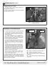
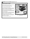
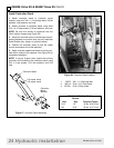
Verification of Control Movements
1. Mount loader to tractor: Remove mount pins
from loader uprights. Align tractor with loader and
slowly drive tractor into loader. Shut off tractor.
2. Connect loader feedline hoses to control valve
hydraulic couplers.
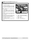
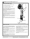
NOTE: At least 6” spacing should be maintained
between valve, bracket, or hoses and any tractor con-
trol (brake pedals, accelerator, hand throttle, or
hydraulic levers).
3. Comply with all Safety Rules and start the tractor.
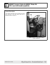
4. Check that all hydraulic control lever positions
operate the loader movements correctly as shown in
Figure 22.
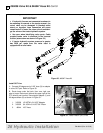
5. If loader movements do not respond correctly,
shut off tractor, relieve pressure, and reconnect prop-
erly. Loader control movements must be correct
before proceeding.
6. Once all loader functions are correct, start the
tractor and operate the loader to check for leaks.
Purge any remaining air from the hydraulic system.
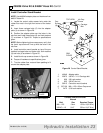
7. When hose routings and correct loader opera-
tions are verified, identify each circuit by placing a
matching colored band around the male and female
quick-disconnect coupler set. The colored bands will
make re-installation easier when the loader is
removed from the tractor
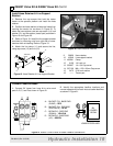
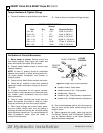
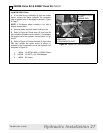
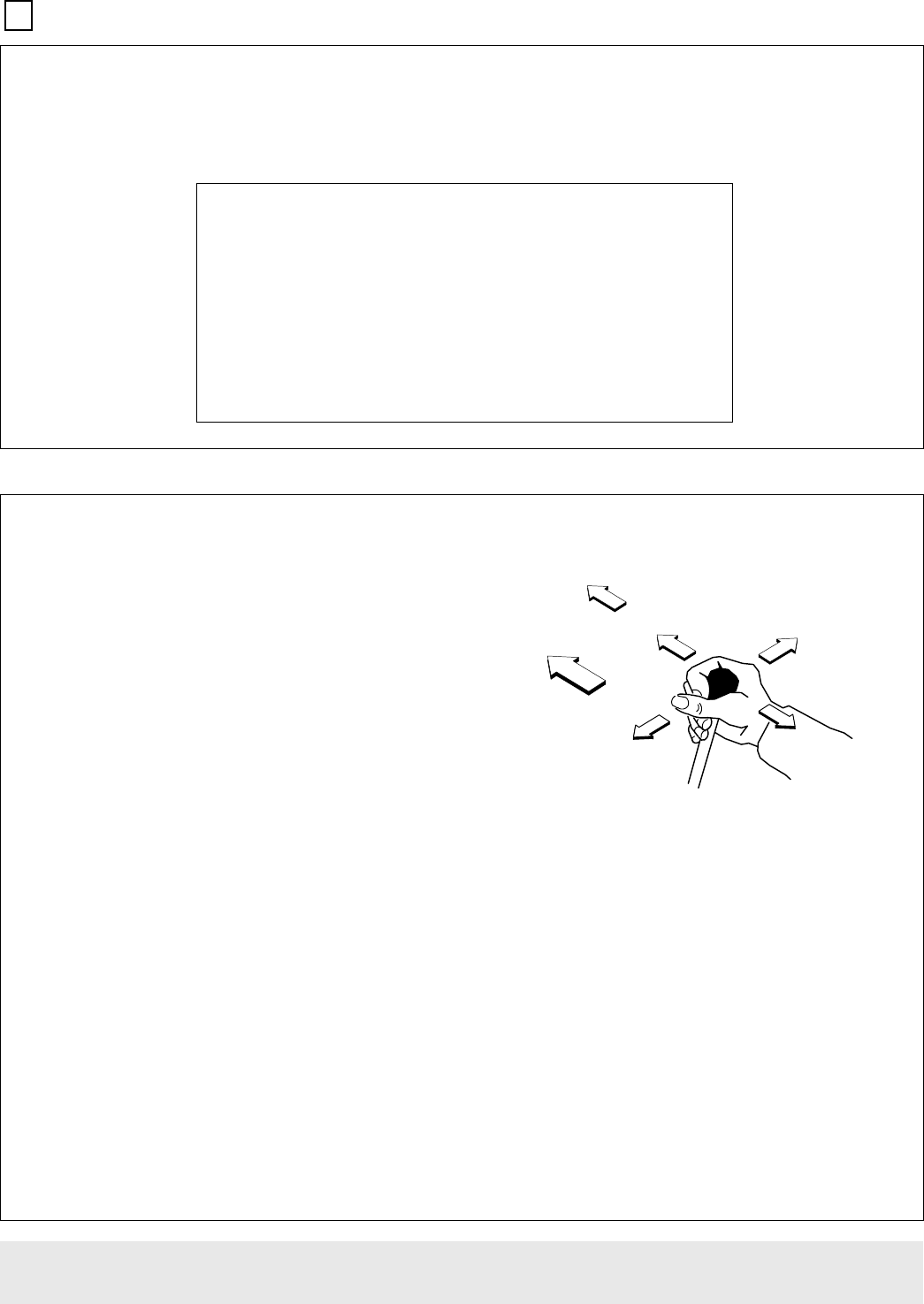
Figure 22 Single Lever Control Operation
● Handle Forward - Boom down
● Handle forward to limit - Float position
● Handle back - Boom up
● Handle to right - Dump bucket or attachment
● Handle to left - Rollback bucket or attachment
8.
Be sure that adequate slack is left in the hoses so
they can move as the loader moves through its full
range of motion.
9. Before operating the loader, make sure that the
Pre-Delivery, Delivery, and Pre-Operation Checklists
from the Operator section in the Loader Operator’s
Manual have been completed.
)/2$7 326,7,21
52//%$&.
/,)7
/2:(5
'803
/(9(5
&21752/
75$&725
)5217