


Hydraulic Installation 19
PN-46018 (Rev. 3/15/02)
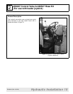
#56037 Valve Kit & #40547 Hose Kit Cont’d
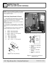
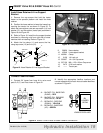
Install Hose Retainer & Line Support
Bracket
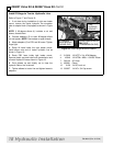
1. Remove the cap screws that hold the tractor
fender to the operator platform and install the hose
retainer.
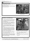
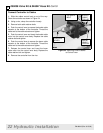
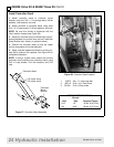
2. Position the hose retainer to keep the hoses from
touching the tractor tire as shown in Figure 20. To
attach the hose retainer, use new cap screw (14), lock
washer (15), and flat washer (tractor part) as shown in
Figure 19 and Figure 20.
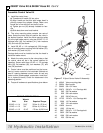
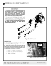
3. Refer to Figure 18. Install the line support bracket
as shown by removing nuts from right side of cross-
member then re-installing. Refer to Figure 19.
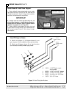
4. Attach the line clamp (11) and secure the line,
using cap screw (13) and nut (12).
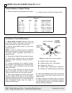
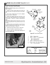
Figure 19 Hose Retainer & Line Support Bracket
Figure 20 Hose Retainer Installed
9. 58859 Hose retainer
10. 40546 Line support bracket
11. 480261 Clamp
12. 6128 1/4 Lock nut
13. 300057 1/4 x 3/4 Cap screw
14. 307129 M8 x 1.25 x 30mm Cap screw
15. 2472 5/16 Lock washer
16. —— Tractor part
2
14
15
9
10
11
12
1
3
TRACTOR
PART
CD5558C-Var
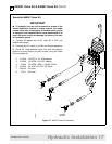
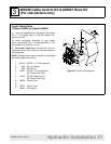
Connect Feedline Hoses
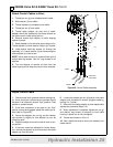
1. Connect 54” hoses from hose kit to valve work
ports A, B, C, and D as shown in Figure 21.
2. Identify the appropriate feedline locations and
connect opposite end of each hose to loader feedlines
as shown in Figure 21.
Figure 21 #56037 Control Valve & Loader Feedline Connections
%
$
&
'
,1
287
3%<
$ %8&.(7 &</ %$6( (1'
'803 5('
% %8&.(7 &</ 52' (1'
52//%$&. %/8(
& %220 &</ 52' (1'
'2:1 <(//2:
' %220 &</ %$6( (1'
83 *5((1
/2$'(5 )(('/,1(6
$%
&
'
5+
/2$'(5
%220