


Hydraulic Installation 23
PN-46018 (Rev. 3/15/02)
#56038 Valve Kit & #46047 Hose Kit Cont’d
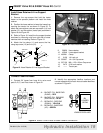
Install Controller Stand Bracket
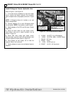
NOTE: Use #46049 adapter plate and hardware from
#46047 Hose Kit.
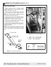
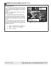
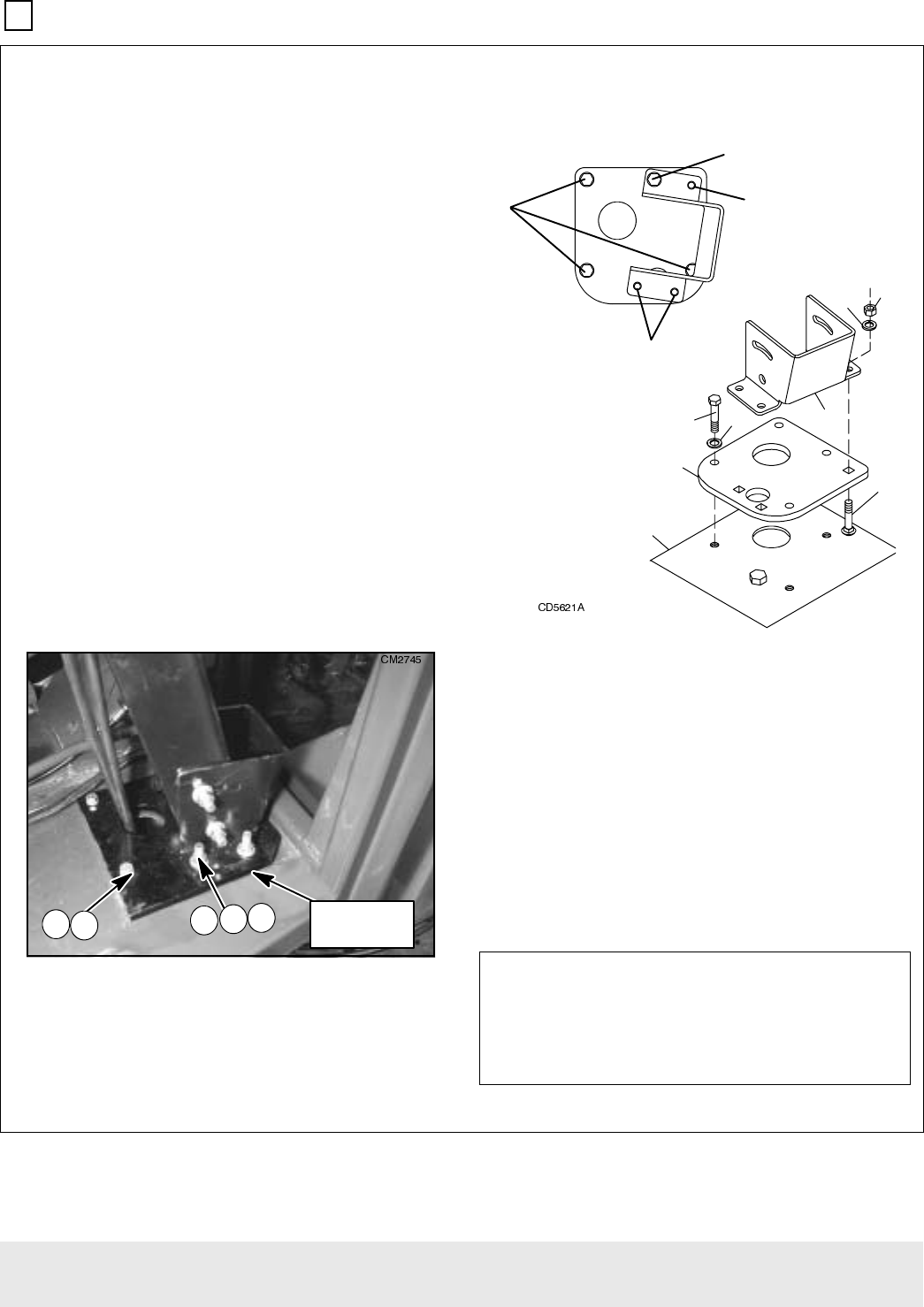
1. Locate the control cable access hole under the
rubber floor mat in the right front corner of the tractor
cab.
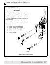
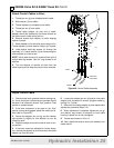
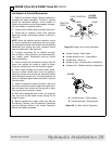
2. Insert three carriage bolts (2) into the adapter
plate (1) as shown in Figure 26.
3. Position the adapter plate over the holes in the
cab floor and install cap screws (6) and lock washers
(7) as shown in Figure 26. Torque to specifications
given.
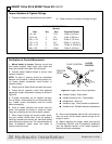
NOTE: Before tightening three cap screws, verify that
the fourth cap screw will line up with the hole in the
cab floor.
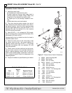
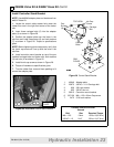
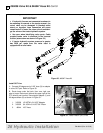
4. Install controller mount bracket on top of the pre
installed carriage bolts and fasten with lock washers
(3) and nuts (4) as shown in Figure 25.
5. Install fourth cap screw as shown in Figure 26.
6. Torque all hardware to specifications given.
7. Trim the rubber floor mat and foam padding to fit
around the adapter plate.
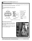
Figure 25 Assembled Control Stand Bracket
Figure 26 Control Stand Bracket
1. 46049 Adapter plate
2. 20973 3/8 NC x 1-1/4 Carriage bolt
3. 838 3/8 Lock washer
4. 835 3/8 NC Hex nut
5. 56215 Controller mount bracket
6. 307129 M8 x 1.25 x 30mm Cap screw
7. 2472 5/16 Lock washer
3
$'$37(5
3/$7(
723 9,(:
&$%
)/225
&DUULDJH
%ROW
&DUULDJH
%ROWV
&DS
6FUHZV
WK &DS
6FUHZ
TORQUE SPECIFICATIONS
Wrench
Bolt Size Required Torque
M8 x 1.25 13mm 15 lbs.-ft.(20 N-m)
3/8 NC x 1.5 9/16” 35 lbs.-ft.(47 N-m)