


T6000 Saber Assembly Section 2-14
ASSEMBLY
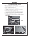
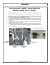
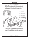
HAND RAIL MODIFICATION
The right side hand rail will need to be removed to allow room for the rear stowing
boom to run along side the cab. To remove the handrail, cut it off at the top and bottom
leaving approximately 2” on the tractor at each end. File the portions that are left to
remove any sharp edges. Plug / cover the portions that are left of the handrail with a
plastic cap.
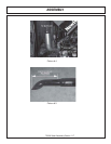
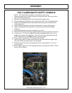
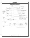
GENERAL HOSE INSTALLATION
Refer to the parts section for detailed information about hoses and fittings for this
application.
When mounting the suction hose between the pump and the tank, the stainless
steel bands that are provided must be used. CAUTION: DO NOT use regular hose
clamps for this purpose. For protection of hoses in contact with metal edges, wrap
hoses with spit hose sections and fasten with hose clamps or zip ties as needed.
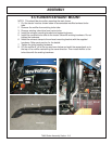
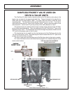
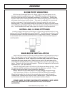
HOSE COVERING
Secure hoses together with zip ties wherever loose. Wrap the hoses between
the main boom and secondary boom with the yellow hose cover, secure with black
string provided. Where hoses may contact the frame or other edges, wrap with split
hose and secure with hose clamps or zip ties. On non cab units the pressure and
return hoses from the control valve will also need to be routed inside the protective
clear hose wrap. Cover the valve, valve fittings with the yellow hose cover and
secure with black string provided.
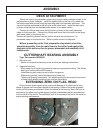
WHEEL WEIGHT MOUNTING
For all machines using a Saber Boom mower, a double wheel weight will be
required for the left side wheel. It will be necessary to mount the large wheel weight
in the wheel using the long cap-screws, lock-washers, flat-washers, and hex nuts per
diagram in the parts section. The smaller wheel weight will need to be used in
addition to the large one. This will be installed as shown in the parts section also.
Installation is most easily done with a small fork lift, inserting a fork in the center
slot of the wheel weight. The head of the cap-screws is to be toward the OUTSIDE
of the weight, with flat-washers on both inside and outside of the assembly. The left
rear tire must also be filled with a mixture of water and calcium chloride at about five
pound per gallon. Tire air pressure should be maintained at approximately 22 P.S.I.
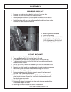
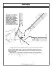
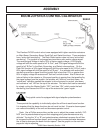
TEMPERATURE GAUGE MOUNTING
(OPTIONAL)
Mount the temperature gauge where it is clearly visible to the operator. Attach the
green ( - ) wire from the negative post on the gauge to a grounded bolt on the tractor
frame. Remove paint if needed to make a good ground. Remove the pipe plug from
the side of the hydraulic reservoir, and install the temperature sensor using thread
sealing tape. Run the white wire from the ( S ) sensor post of the gauge to the
temperature sensor on the hydraulic reservoir tank.
Install lynch pin provided through hole on boom rest pin.