MAINTENANCE
Saber Maintenance Section 4-26
©2011 Alamo Group Inc.
MAINTENANCE
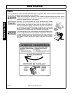
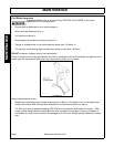
DO NOT re-use the locking hex nuts for mounting the knives. If hex nut becomes
loose, or required removal for knife replacement or any other reason, they must be
discarded and replaced with new nuts.
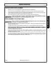
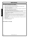
63” BOOM FLAIL KNIFE REPLACEMENT
1. If knives are damaged or badly worn, they will need to be replaced as a set. Replacing a single knife
can cause severe vibration and possible damage to the mower.
2. Assemble knives, clevis, bolts and nuts as shown in part section of manual.
3. Install locking hex nut so that the flat face of nut is towards the knife.
4. Apply loctite “271” or equivalent to threads.
5. Torque nut to 52 FT. LBS. Knife must swing freely.
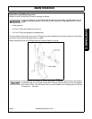
DO NOT re-use the locking hex nuts for mounting the knives. If hex nut become loose,
or require removal for knife replacement or any other reason, they must be discarded
and replaced with new nuts.
Knives should not be welded on for any reason.
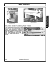
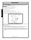
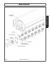
REPLACING HAMMER KNIVES (SABER)
If knives are damaged or badly worn, they will need to be replaced as a set. Replacing a single knife can cause
severe vibration and possible damage to the mower. The knives should not be welded on for any reason.
When replacing knives, replace bushings, bolts and locknuts.
Apply Loctite® “271” or equivalent to threads and install the locking hex nuts so that the flat face of the nut is
towards the knife. Torque the hex nut to 159 ft. lbs.
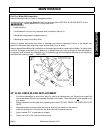
DO NOT re-use the locking hex nuts for mounting the knives. If hex nut becomes
loose, or require removal for knife replacement or any other reason, they must be
discarded and replaced with new nuts.
Knives should not be welded on for any reason.
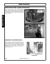
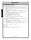
SABER FLAIL CUTTERSHAFT BEARING INSTALLATION
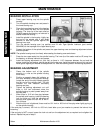
1. Clean both ends of cuttershaft.
2. Grease bearing assemblies by hand including the seal
3. Insert drive end of cuttershaft through side plate of bonnet assembly. Slide other end into slot of
opposite side plate and center shaft in bonnet assembly.
4. CAUTION: Carefully slide bearing assemblies (seal side first) over end of shaft. Install retaining washer
and nut onto threaded end of taper lick sleeve, but do not tighten. DO NOT SUPPORT THE
CUTTERSHAFT WITH THE BEARING ASSEMBLIES AT THIS TIME. SUPPORT THE
CUTTERSHAFT AT THE DRUM. Ensure the cuttershaft is centered in bonnet assembly, then carefully
slide bearing assemblies into place against bonnet side plate. (Note: The seal at inside of bearing
assembly must slide over 2-1/4” O.D. seal surface at end of shaft drum.) Temporarily bolt the bearing
assemblies to the side plate with two (2) bolts and standard nuts.
5. Tighten taper locknuts until taper lock sleeves are snug to shaft and inside of bearings, nuts and
retaining washers are snug against bearings. Then turn nuts another 1/4 turn plus enough to align
notch in nuts with a locking tab on the retaining washer. Bend locking tab into notch of nut.


