


T6000 Saber Assembly Section 2-13
ASSEMBLY
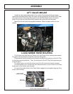
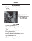
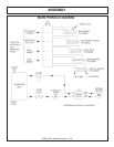
MAIN FRAME MOUNTING
With an overhead hoist and / or jack-stands, raise one side of the frame up to the
correctly matching mounting holes. Install cap-screws and all other hardware as
shown in main frame parts section to secure the first side to the tractor casting.
Next raise the second side of the frame into position and secure to tractor as done
on first side. Now the ten capscrews, lockwashers and hex nuts can be installed to
join the two halves of the main frame together. Remove the cap-screws that secure
the main frame to the tractor one at a time and apply a thread locking agent.
Reinsert the cap-screws and tighten / torque to values noted in the torque chart
located in the maintenance section of this manual.
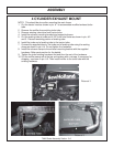
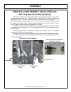
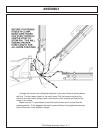
FRONT PUMP MOUNTING
Install the pump mounting bracket on the front of the tractor with cap-screws and
lock-washers as shown in the parts section illustration. DO NOT tighten fasteners
at this time.
Slide the pump drive shaft into the crankshaft adapter. The end with the shorter
splines should be inserted into the adapter (if applicable).
Slide the splined drive shaft coupler onto the pump drive shaft. Install the pump
onto the mounting bracket. NOTE: the shaft is offset to one direction, the pump
should be installed with the offset side on top. Install hardware for securing pump to
the pump mount, DO NOT tighten.
Align pump so that splined coupling can be moved back and forth by hand.
Tighten pump mounting bolts in succession rechecking for spline coupling
movement. Remove the pump mounting bracket bolts one at a time and apply a
tread locking agent. Tighten these bolts in succession, again checking for free
movement in the drive shaft. After all bolts are torqued, the end play on the drive
shaft should be 1/16” to 1/8”, and coupler should move freely with hand pressure. If
end play is less than 1/16”, grind the end of the shaft to achieve the proper end play.
If there is more than 1/4" of end play, return the shaft with specifications for a longer
shaft.
CAUTION: DO NOT START THE TRACTOR UNTIL ALL HOSES ARE
ATTACHED, TANK IS FILLED WITH PROPER OIL AND BALL VALVES ARE
OPEN! STARTING AT THIS TIME WILL CAUSE SERIOUS DAMAGE TO THE
PUMP.
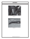
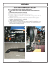
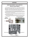
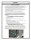
HYDRAULIC TANK INSTALLATION
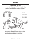
Install all fittings and tubes into tank and tank filter as shown in parts section
illustration. Insert tank sight glass into front side of the tank. Install the temperature
sensor (optional) or pipe plug into the side of the tank.
Place the tank in the mounting bracket on the main fame as shown in the parts
section.
Secure the tank in the mounting bracket with the tank strap and nylock nuts.
Install the filter gauge into the filter housing so that it points to the rear of the
tractor and is clearly visible to the operator.
The breather cap will be installed after tank is filled.