


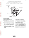

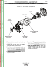
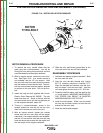


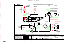

ROTOR
THRU-BOLT
FIGURE F.18 – ROTOR WITH STATOR REMOVED
STATOR/ROTOR REMOVAL AND REPLACEMENT (continued)
ROTOR REMOVAL PROCEDURE
1. To remove the rotor, double check that the
spark plug wire is disconnected. You will be
turning the rotor during this procedure, and this
could accidentally cause engine kickback.
2. With an impact wrench, remove the rotor thru-
bolt. See Figure F.18. If an impact wrench is
not available, use the 1/2” box wrench. Hold
the rotor with one hand and shock the wrench
with the mallet to loosen the thru-bolt. The thru-
bolt has a star washer and lock washer, beveled
to conform to the rotor shaft. Pull out the thru-
bolt.
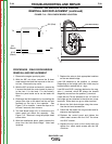
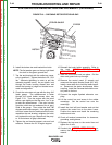
3. Install the long thru-bolt supplied with Lincoln
Electric Rotor Removal Kit S20925. The slot
head must face out. Screw in the bolt with the
slot head screw driver until the bolt bottoms out
on the engine crankshaft, about 3/4”.
4. Turning it counterclockwise, screw in the
reverse thread bolt from the kit into the rotor
shaft until it bottoms out on the thru-bolt.
5. With an impact wrench, tighten the reverse
thread bolt until the rotor pops off the engine
crankshaft. If an impact wrench is not available,
use the 1/2” box wrench. Hold the rotor with one
hand and shock the wrench with the mallet until
the rotor pops off the engine crankshaft.
6. Slide the rotor and blower (press-fitted to the
rotor) the rest of the way off the crankshaft.
REASSEMBLY PROCEDURE
1. Lubricate the tapered engine crankshaft. Slide
the rotor onto the shaft.
2. Coat the rotor thru-bolt threads with Lincoln
E177-R retaining compound (Locktite( 277).
Place the beveled lock washers onto the thru-
bolt and insert it into the rotor shaft. Hold the
rotor and tighten the thru-bolt to 22 - 25 ft lbs.
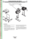
3. Carefully install the stator, with the leads at the
1 o’ clock position. IMPROPER HANDLING OF
THE STATOR CAN RESULT IN SHORTED
WINDINGS AND/OR LOST OUTPUT.
4. Install the end bracket. Slide it on and install
the two top thru-bolts loosely to hold the end
bracket for the next step.
5. Install the end bracket support.
TROUBLESHOOTING AND REPAIR
F-47 F-47
BULLDOG® 140
Return to Section TOC Return to Section TOC Return to Section TOC Return to Section TOC
Return to Master TOC Return to Master TOC Return to Master TOC Return to Master TOC