


ROTOR “FLASHING” CIRCUIT TEST (continued)
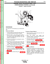
MOVING PARTS can injure.
Keep away from moving parts.
-------------------------------------------------------------------
ENGINE EXHAUST can kill.
Use in open, well ventilated areas or
vent exhaust to the outside.
-------------------------------------------------------------------
5. Start the engine and run it at High Idle (3700 -
3800 RPM).
6. The DC ammeter should read between 0.15
and 0.30 amps.
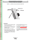
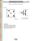
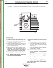
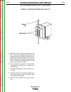
7. If the DC ammeter reads 0.0 amps, check for
flashing voltage between lead #202 from the
brush holder and case ground (lead #201). See
Figure F.4, and the Wiring Diagram. Normal
flashing voltage is 2.05 VDC.
8. If normal flashing voltage is present, perform
the Rotor Resistance Test. Also be sure that
all #201 leads have continuity (zero ohms) to
case ground.
9. If flashing voltage is not measured, check from
lead 205 on the diode bridge D3 to case
ground. Normal readings are around 3 VAC. If
no flashing voltage is present, the engine mag-
neto may be faulty. Check lead 205 back to
magneto and measure for voltage there.
10. If there is AC volts at the diode bridge, the
diode may be open. Check diode and move
leads over if need be.
TROUBLESHOOTING AND REPAIR
F-19 F-19
BULLDOG® 140
WARNING
Return to Section TOC Return to Section TOC Return to Section TOC Return to Section TOC
Return to Master TOC Return to Master TOC Return to Master TOC Return to Master TOC