


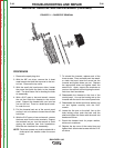
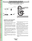

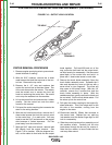
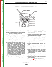


BEARING BRACKET
END COVER
END BRACKET
MACHINING
STATOR LAMINATION
ASSEMBLY
THRU BOLT
ROTOR
BRUSH
ASSEMBLY
FIGURE F.15 – GENERATOR COMPONENTS
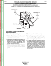
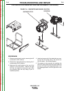
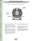
STATOR/ROTOR REMOVAL AND REPLACEMENT (continued)
6. Remove the brush assembly from the slip ring
end bracket.
7. Remove the (4) long HHCS and hardware
along with the slip ring end bracket.
8. Carefully remove the stator from the engine end
bracket and cradle. IMPROPER HANDLING
OF THE STATOR CAN RESULT IN SHORTED
WINDINGS AND/OR LOST OUTPUT.
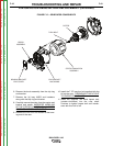
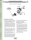
9. Remove the rotor thru bolt located at the bear-
ing end of the rotor.
10. Install the 7.70” long thru bolt supplied with the
kit into the rotor. THREAD BOLT UNTIL TIGHT
TO ENGINE CRANKSHAFT.
11. Install the supplied, left hand impact bolt,
(counter-clockwise) into the rotor shaft.
Continue to tighten impact bolt until interfer-
ence with thru bolt is felt.
TROUBLESHOOTING AND REPAIR
F-43 F-43
BULLDOG® 140
Return to Section TOC Return to Section TOC Return to Section TOC Return to Section TOC
Return to Master TOC Return to Master TOC Return to Master TOC Return to Master TOC