


OPERATION
B-3 B-3
BULLDOG® 140
LIMITATIONS
• The Bulldog® 140 is not recommended for any
processes besides those that are normally per-
formed using stick welding (SMAW) procedures.
• The Bulldog® 140 is not recommended for pipe
thawing.
• During welding, generator power is limited to 100
watts, and output voltages can drop from 120 to 80
volts and 240 to 160 volts. Therefore, DO NOT
OPERATE ANY SENSITIVE ELECTRICAL EQUIP-
MENT WHILE YOU ARE WELDING.
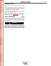
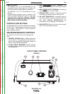
CONTROLS AND SETTINGS
All welder/generator controls are located on the Output
Control Panel. Gasoline engine controls are mounted
on the engine. See Figure B.1 and the figures in
engine operation section.
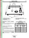
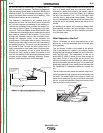
WELDER/GENERATOR CONTROLS
See Figure B.1 for the location of the following fea-
tures:
1. CURRENT CONTROL DIAL: Adjusts continuous
current output. The amperages on the dial corre-
spond to the approximate amperages needed for
specific Lincoln welding electrodes.
2. 20 AMP CIRCUIT BREAKER: Provide separate
overload current protection for the 120 Volt and 240
Volt Receptacles
3. WELD ELECTRODE OUTPUT TERMINAL: Pro -
vides the connection point for the electrode holder
cable.
4. WELD WORK OUTPUT TERMINAL: Provides the
connection point for the work cable.
5. GROUND STUD: Provides a connection point for
connecting the machine case to earth ground.
6. 240 VOLT RECEPTACLE: Connection point for
sup 240 Volt power to operate one electrical device.
7. 120 VOLT DUPLEX RECEPTACLES (2):
Connection point for supplying 120 Volt power.
8. HOUR METER: Records the time that the engine
has run for maintenance purposes.
1
2
6
7
8
5
3
4
OUTPUT PANEL CONTROLS
FIGURE B.1
Return to Section TOC Return to Section TOC Return to Section TOC Return to Section TOC
Return to Master TOC Return to Master TOC Return to Master TOC Return to Master TOC