


OPERATION
B-8 B-8
BULLDOG® 140
WELDING OPERATION
GENERAL INFORMATION
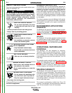
ELECTRIC SHOCK can kill.
• Do not touch electrically live parts or
electrodes with your skin or wet cloth-
ing.
• Insulate yourself from the work and ground.
• Always wear dry insulating gloves.
------------------------------------------------------------------------
The Bulldog® 140 has a voltage of up to 66 Volts AC
which can shock. The Bulldog® 140 generator/welder
can deliver from 70 to 125 amps of continuous welding
output current. Output can be adjusted by setting the
current control dial on the output control panel.
You can get maximum welding output by setting the
dial to 125 AMPS. At high current settings like this,
some output may decrease as the machine is used. If
you are welding for a long time, you may need to turn
the dial slightly upward to maintain the same results.
The numbers on the dial correspond to the average
amps needed to weld using specific Lincoln welding
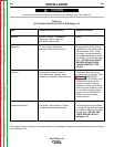
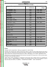
rods. Table B.2, WELDING APPLICATIONS, gives
you the recommended dial settings based on the thick-
ness of the work and the size and type of rod you’re
using.
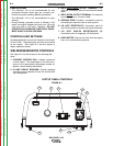
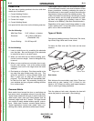
TO USE THE Bulldog® 140 FOR WELDING:
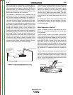
1. Remove the flange nuts from the weld output ter-
minals and place the work and electrode welding
cables over the terminals. (See Figure B.1)
Replace and tighten the flange nuts securely. Be
sure the connections are tight.
2. Select the appropriate electrode. (See Table B.2)
WELDING APPLICATIONS, or the ELECTRODE
SELECTION GUIDE on the machine Output
Control Panel.
3. Attach the work clamp securely to the work you are
welding.
4. Insert the electrode into the electrode holder.
5. Set the current control dial to the desired output
current.
6. Start the gasoline engine. See ENGINE OPERA-
TION in this section of the manual.
7. Strike an arc and begin welding. For information
on welding techniques, see WELDING GUIDE-
LINES in this section of the manual.
AFTER YOU FINISH THE WELD:
1. Stop the gasoline engine. See ENGINE OPERA-
TION in this section of the manual.
2. Allow the electrode and work to cool completely.
3. Remove the work clamp from the work.
4. Remove any remaining piece of electrode from the
electrode holder.
5. If you are finished using the Bulldog® 140 for weld-
ing, disconnect the welding cables from the weld
output terminals. Reattach the flange nuts and
leave them on the terminals.
NOTE: 1. Welding current is continuously variable
with 60% duty cycle applying to output
currents 100 Amps and less and 30%
duty cycle applying to currents above 100
Amps.
2. Duty cycle is based on a ten minute peri-
od. The welder can be loaded to 125
Amps for three minutes out of every ten
minute period or to 100 Amps for six min-
utes out of every ten minute period.
CONTROL FUNCTION / OPERATION
“Current Control Dial”
Provides welding current adjustment from 70 through
125 Amps.
To obtain maximum weld output, turn the “Current
Control Dial” to “125 Amps” for either a cold or hot
engine. As the machine is used, some welding voltage
may decrease at high current settings. If you are weld-
ing for long periods of time, the dial may need to be
slightly turned upward to provide the same welding
results as when the machine was cold.
The numbers listed on the dial correspond to the aver-
age amperage needed to weld specific Lincoln rods.
Refer to Table B.2 “Welding Application Guide” and
“Electrode Selection Guide” listed on the machine
nameplate for proper current and electrode settings.
WARNING
Return to Section TOC Return to Section TOC Return to Section TOC Return to Section TOC
Return to Master TOC Return to Master TOC Return to Master TOC Return to Master TOC