


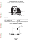


SLIP
RINGS
201A(-)
202A(+)
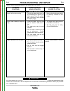
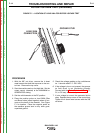
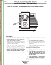
FIGURE F.3 – BRUSH HOLDER LEADS 201(-) AND 202B (+)
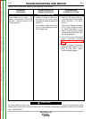
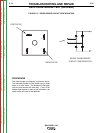
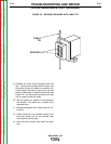
FIGURE F.4 – DIODE BRIDGE LEAD ASSIGNMENTS
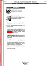
ROTOR “FLASHING” CIRCUIT TEST (continued)
PROCEDURE
1. With the 3/8” nutdriver, remove the 20 sheet
metal screws that hold the top cover to the con-
trol box. Remove the top cover.
2. Locate and remove lead #201A from the brush
holder. See Figure F.3 for location.
3. Connect the negative (-) lead of the DC amme-
ter to lead #201A and the positive (+) lead to the
brush holder.
4. Remove lead #7 from field diode bridge rectifier
D2. See Figure F.4. Electrically isolate the
lead.
TROUBLESHOOTING AND REPAIR
F-18 F-18
BULLDOG® 140
7
201
201
9
200
+
–
200C
Return to Section TOC Return to Section TOC Return to Section TOC Return to Section TOC
Return to Master TOC Return to Master TOC Return to Master TOC Return to Master TOC