


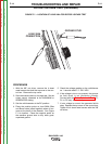
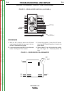
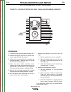

SLIP
RINGS
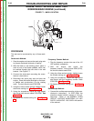
FIGURE F.5 – LOCATION OF ROTOR SLIP RINGS - BRUSH HOLDER ASSEMBLY REMOVED
ROTOR RESISTANCE TEST (continued)
PROCEDURE
1. Conduct the test with the gasoline engine OFF.
2. Remove the spark plug wire to prevent acci-
dental engine kickback or starting.
3. Isolate the rotor electrically by removing the
generator brushes. Refer to Figure F.5 as you
perform the remaining steps.
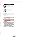
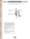
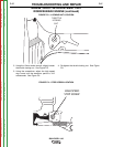
4. Open the brush holder assembly cover.
Squeeze the 2 tabs and depress the cover at
the top with a screw driver or your fingernail.
The cover will drop open on its bottom hinge.
5. With the 1/4” nut driver, remove the 2 screws
that hold the brush holder assembly in place.
6. Slide the brush holder assembly out and lay it
aside, held by the 2 wires attached.
7. Measure the resistance across the rotor slip
rings.
A. Set the ohmmeter on the low scale (X1).
B. Place one meter probe on one of the rotor
slip rings. Place the other probe on the
other slip ring.
C. Check the resistance across the slip rings.
It should read 7 - 9 ohms.
8. Measure the resistance to ground.
A. Set the ohmmeter on the high scale
(X100,000).
B. Place one probe on either of the slip rings.
Place the other probe on any good,
unpainted ground. Use the ground stud or
the rotor thru-bolt.
C. Check the resistance. It should read very
high, at least .5 megohm (500,000 ohms).
If the resistance checks meet the specifications,
then the rotor is okay.
TROUBLESHOOTING AND REPAIR
F-22 F-22
BULLDOG® 140
Return to Section TOC Return to Section TOC Return to Section TOC Return to Section TOC
Return to Master TOC Return to Master TOC Return to Master TOC Return to Master TOC