


OUTPUT PROBLEMS
Observe Safety Guidelines detailed in the beginning of this manual.
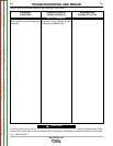
PROBLEMS
(SYMPTOMS)
POSSIBLE AREAS OF
MISADJUSTMENT(S)
RECOMMENDED
COURSE OF ACTION
If for any reason you do not understand the test procedures or are unable to perform the tests/repairs safely,
contact the Lincoln Electric Service Department for technical troubleshooting assistance before you proceed.
Call 1-888-935-3877.
CAUTION
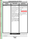
No weld output and no auxiliary out-
put - engine runs normally.
1. The generator brushes may be
worn or faulty. See the Main -
tenance Section of this manual
or contact your local Lincoln
Electric Authorized Field Ser -
vice Facility.
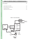
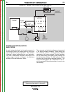
1. Perform the Rotor Voltage
Test.
2. If the rotor voltage is zero to 3
VDC, check the flywheel alter-
nator and associated wires
200A, 202, and 202A for conti-
nuity. The voltage from lead
200A to ground should be at
least 18 to 21 VDC at (3700
RPM). Normal voltage is 37.5-
42.5VDC. If the voltage is low
or missing, the flywheel alterna-
tor may be faulty. See the
Wiring Diagram. Check diode
D3 & lead #202C
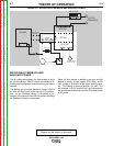
3. Check lead 201B (green) for
con tinuity (zero ohms) to
ground. See wiring diagram.
4. The field capacitor (C1) or
bridge (D2) may be faulty. Test
or replace.
5. Test the rheostat (R1). Normal
resistance is 3.3 ohms. See the
Rheostat Removal and
Replacement Procedure.
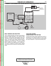
6. The rotor may be faulty. Per -
form the Rotor Resistance
Test.
7. Perform Flashing Circuit Test.
TROUBLESHOOTING AND REPAIR
F-5 F-5
BULLDOG® 140
Return to Section TOC Return to Section TOC Return to Section TOC Return to Section TOC
Return to Master TOC Return to Master TOC Return to Master TOC Return to Master TOC