


OPERATION
B-6 B-6
BULLDOG® 140
GENERATOR OPERATION
Be sure that any electrical equipment plugged into
the generator’s AC power receptacles can with-
stand a ±10% voltage and a ±4% frequency varia-
tion. Some electronic devices cannot be powered
by the Bulldog® 140. Refer to Table A.2, ELECTRI-
CAL DEVICE USE WITH THE Bulldog® 140, in the
INSTALLATION section of this manual.
------------------------------------------------------------------------
GENERAL INFORMATION
The Bulldog® 140 generator is rated at 4000 continu-
ous watts (5500 surge watts). It provides both 120 volt
and 240 volt power. You can draw up to 20 amps from
either side of the 120 volt duplex receptacle, but no
more than 33.3 amps from both sides at once. Up to
16.7 amps can be drawn from the single 240 volt
receptacle.
Electrical loads in watts are approximately calculated
by multiplying the voltage rating of the load by the num-
ber of amps it draws. (This information is given on the
load device nameplate.) For example, a device rated
120 volts, 2 amps will need 240 watts of power (120 x
2 = 240).
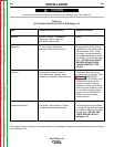
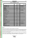
You can use Table B.1, GENERATOR POWER
APPLICATIONS, to determine the wattage require-
ments of the most common types of loads you can
power with the Bulldog® 140. Be sure to read the
notes at the bottom of the table.
TO USE THE Bulldog® 140 AS AN AUXILIARY
POWER SUPPLY:
1. Start the gasoline engine. See ENGINE OPERA-
TION in this section of the manual and the engine
owner’s manual.
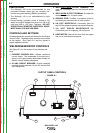
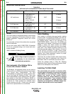
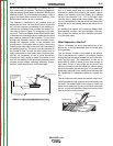
2. Set the current control dial on the output control
panel to “GENERATOR”. See Figure B.1.
3. Plug the load(s) into the appropriate 120 volt or
240 volt power receptacle.
NOTE: During welding, the maximum generator out-
put for auxiliary loads is 100 watts.
NOTE: You can supply multiple loads as long as the
total load does not exceed 5,500 surge watts
or 4,000 Continuous watts. Be sure to start the
largest loads first.
STOPPING THE ENGINE
1. Remove all welding and generator power loads
and let the engine cool by running it for several
minutes.
2. Stop the engine by placing the “ON/OFF” switch in
the “OFF”(O) position.
3. Close the fuel shutoff valve.
Close the fuel valve when the machine is trans-
ported to prevent fuel leakage from the carburetor.
For long periods of storage, turn off the fuel shut-
off valve and let the engine run until there is no
more fuel in the line. Use a fuel additive such as
Sta-Bil to minimize fuel gum deposits.
------------------------------------------------------------------------
RUNNING THE ENGINE
The engine is set at the factory to run at high idle
speed when not under load. You should not adjust this
setting yourself.
BREAK-IN PERIOD
The engine will use a greater amount of oil during its
“break-in” period. Check the oil frequently during
break-in. For more details, see the MAINTENANCE
section in the engine owner’s manual.
During break-in, the unit should be subjected to
moderate loads. Before stopping the engine,
remove all loads and allow the engine to cool sev-
eral minutes.
------------------------------------------------------------------------
LOW OIL SENSING
This engine has a built in sensor which responds to low
oil level (not pressure). When activated, the system will
shut the engine down. The engine will not restart untill
sufficient oil is added. Check oil level frequently and
add oil as required to the full mark on the dipstick. (DO
NOT OVERFILL)
WARNING
CAUTION
CAUTION
Return to Section TOC Return to Section TOC Return to Section TOC Return to Section TOC
Return to Master TOC Return to Master TOC Return to Master TOC Return to Master TOC