


TP-5695 12/936-14 Installation
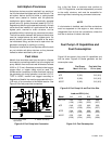
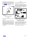
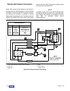
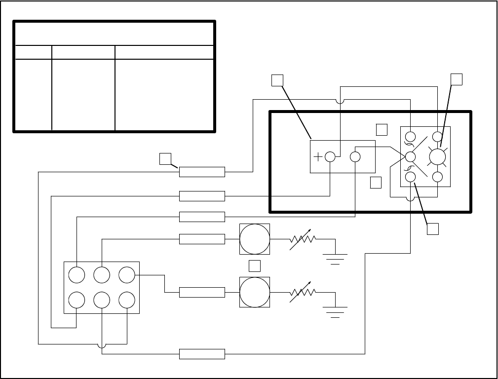
Remote Start Switch Connection
Kohler offers several remote panels for connection to
the generator set. See Accessories for further detailed
description. A wiring harness with a connector keyed to
the controller box connector is available to connect
these panels to the generator set. The other end of this
harness has pigtails which can be used if the installer
elects to use just a start-stop switch or separate lights
and hourmeter. See Figure 6-22.
NOTE
If gauges are to be used, there must also be generator
set senders. Senders are optional on these generator
sets. Gauges and senders are available as service
items from an authorized Kohler service
dealer/distributor.
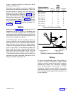
WT
OP
1 2 3
4 5 6
J3
Lead Designations
Pin Lead Function
J3-1 Black Ground (--)
J3-2 Tan Water Temp. Ga.
J3-3 Lt. Blue Oil Pressure Ga.
J3-4 Violet Gen. “ON” (+)
J3-5 Yellow/Red Start
J3-6 Grey/Black Stop
NOTE
All wire is 16 gauge.
Tape to insulate all
unused lead ends.
1
2
3
4
6
7
5
1. Use Insulink or Solder Connection (Tape to Insulate)
2. Hourmeter
3. “ON” Light
4. Stop
5. Start
6. Rocker Switch
7. Gauges Senders
Figure 6-22. Remote Control Panel Wiring