


TP-5695 12/93 Installation 6-11
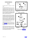
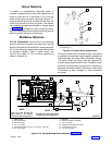
Above Waterline
In addition to considerations described earlier, a
customer-supplied silencer should be installed with its
outlet at a maximum of 10 horizontal ft. (3 m) from the
center of the engine’s exhaust outlet (see Figure 6-17).
A typical silencer should be mounted with the inlet and
outlet level and with the drain plug down. The silencer
may require two supporting brackets or hanger straps
for installation to stringers or other suitable structure.
Any “lift” in the exhaust line to improve silencing must be
below the engine exhaust manifold outlet.
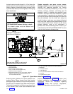
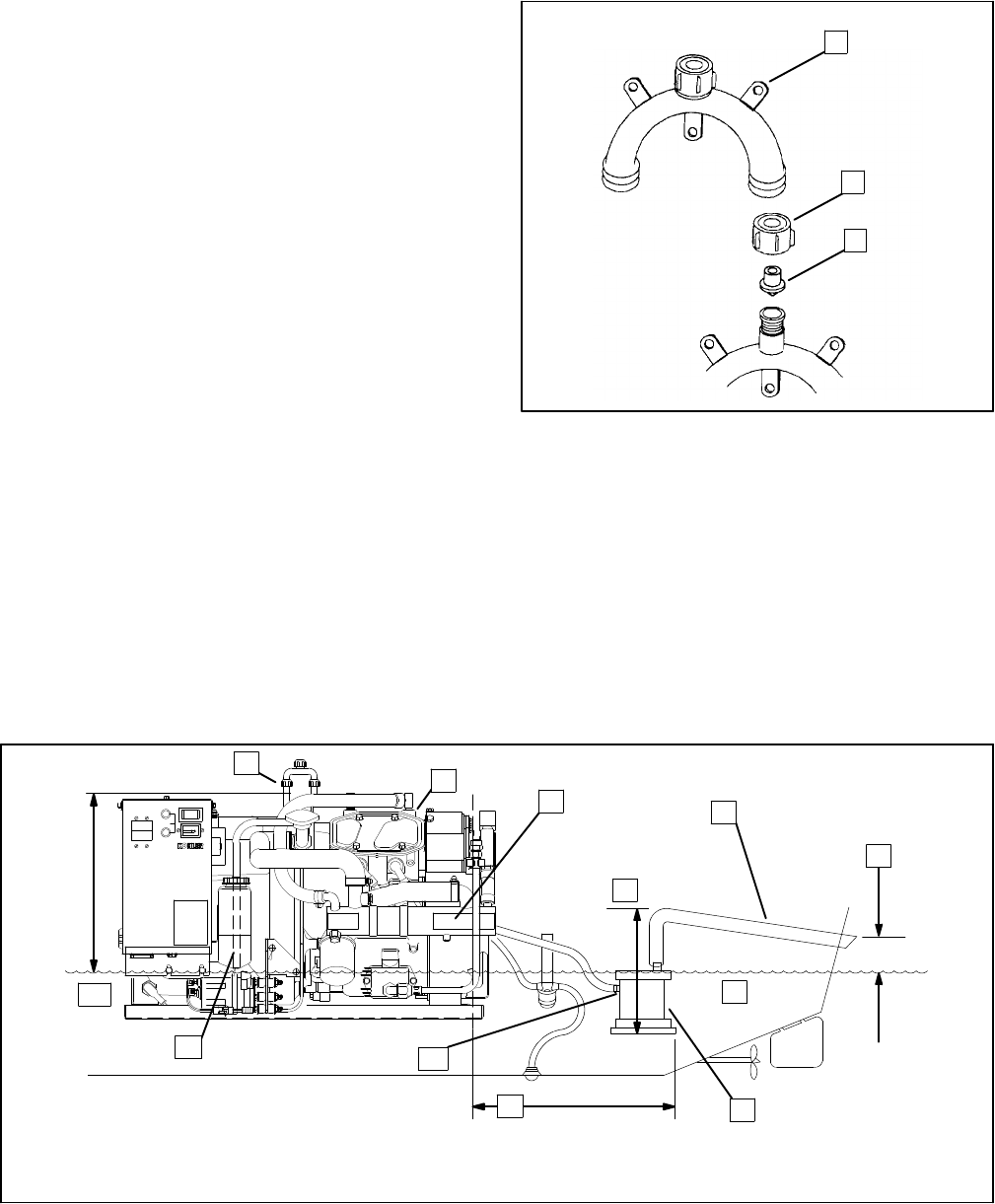
Mid/Below Waterline
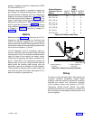
U.S.C.G. Regulations require that an anti-siphoning
provision be used to prevent raw water entry into the
engine if the exhaust manifold outlet is located less than
9 in. (23 cm) above the waterline when the craft is loaded
to maximum capacity. Install a siphon break, see
Figure 6-18, at least 1 ft. (31 cm) above waterline as
shown in Figure 6-19.
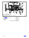
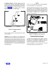
1
2
3
1. Mounting Base
2. Retaining Cap
3. Reed Valve Assembly
1-779
Figure 6-18. Siphon Break Components
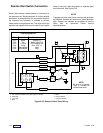
The siphon break must be located at least 1 foot above
the waterline at maximum vessel capacity between the
heat exchanger and water elbow (three-way fittings).
The siphon break and fitting must be supported to
maintain proper position and function. The siphon break
should be mounted directly vertical of its connection to
generator set where possible. Otherwise, a slight offset
is allowable to clear stringers or other permanent
structures.
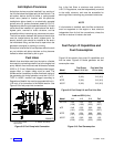
1. Siphon Break
2. Exhaust Manifold
3. Heat Exchanger
4. 4 ft. (1.2 m) Max.
5. Exhaust Hose Slope 0.5 in. (1.3 cm) per ft. (30.5 cm)
6. 4 in. (10 cm) Min.
7. Waterline
8. Silencer (Customer Supplied)
9. 10 ft. (3 m) Max.
10. Install Optional Water Lock Here
11. Coolant Recovery Tank
12. 1 ft. (30.5 cm) Min.
TOTAL HOURS
00 000
1/10
10A
FUSE
BATT.
CHRG.
INPUT
NOTE
Use two hose clamps on
each end of all flexible
exhaust hose connections.
NOTE
Data given is also applicable
to side-exhaust installations.
4
5
6
7
8
9
10
11
12
STOP/START
1
2
3
258000-D
Figure 6-19. Typical Mid and Below Waterline Installation