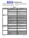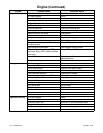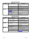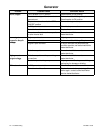
TP-5695 12/93 Wiring Diagrams 5-5
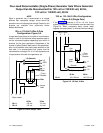
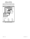
120/240- or 110/220-Volt
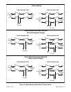
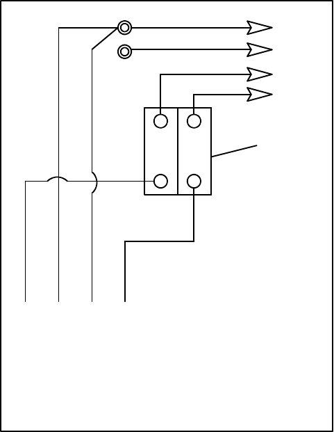
Configuration--Figure 5-6
Jumper lead not used. If unit was originally wired for
straight 120 or 110 volt, be sure jumper lead is removed
(see Figure 5-6 for location). Leads L1 and L2 are
different phases and must never be connected together.
4 3 2 1
Stator Leads
LO
GRD.
L2
L1
LO (Neutral)
Load Side
Line Side
Circuit
Breaker
Ground
60 Hz 50 Hz
L0--L1 120 volt 110 volt
L0--L2 120 volt 110 volt
L1--L3 240 volt 220 volt
Figure 5-6. Without Jumper Lead


