TP-5695 12/936-6 Installation
Anti-Siphon Provisions
Anti-siphon devices must be installed if any section of
fuel line lies below the highest point of the fuel tank. The
anti-siphon device should be either a spring-loaded
check valve (tested to function with the particular
installation’s siphon head), or an electrically operated
shutoff valve (UL ignition-protected, tested to U.S.C.G.
Regulations) which may be operated manually. A check
valve should be installed at a point above fuel tank’s
highest point, secured to craft’s structure, and be
accessible without removing any permanent structure.
The fuel line section between the tank and check valve
must be located above the tank’s highest point. An
electric shutoff valve should be installed at the tank’s
fuel withdrawal fitting, and be wired to open when the
generator set engine is cranking or running.
Anti-siphon holes drilled in fuel dip tubes within the tank
are not reliable anti-siphon devices as they become
ineffective when restricted by dirt or gum.
Fuel Lines
Metallic lines should be used from the tank to a flexible
hose section connecting metallic line to the engine fuel
pump. Metallic lines must have wall thickness of at least
0.029 in. (0.74 mm). Seamless annealed nickel copper,
copper-nickel, or copper tubing must be used. The
flexible section (necessary to allow vibrational motion of
the generator set during operation) must be U.S.C.G.
TYPE A HOSE, marked and tagged according to
Regulations. Metallic line must be supported within 4 in.
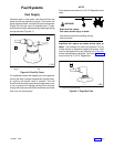
(102 mm) of its connection to the flexible section. See
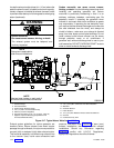
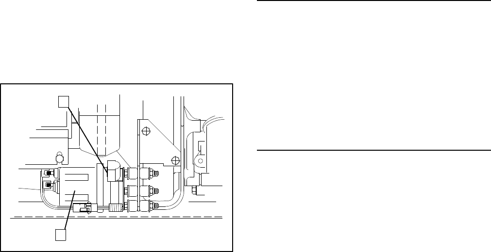
Figure 6-8 for fuel pump inlet connection.
1. 1/4 in. NPT Female
Pipe Thread
2. Electric Fuel Pump
1
2
258000-D
Figure 6-8. Fuel Pump Inlet Connection
Any in-line fuel filters or strainers must conform to
U.S.C.G. Regulations, must be independently mounted
to the craft’s structure, and must be accessible for
servicing without removing any permanent structures.
NOTE
If a fuel strainer is installed, each fuel filter and strainer
must be supported on the engine or boat structure
independent from its fuel line connections, unless the
fuel filter or strainer is inside a fuel tank.
Fuel Pump Lift Capabilities and
Fuel Consumption
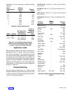
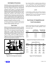
Figure 6-9 lists electric fuel pump lift capabilities and
fuel line sizes. Figure 6-10 shows generator set fuel
consumption rates.
Model
Fuel Pump
Max. Lift ft. (m)
Fuel Inlet Size
I.D. in. (mm)
3.5CFZ 3 (0.9) 3/8 (9.5)
4CZ 3 (0.9) 3/8 (9.5)
5CFZ 3 (0.9) 3/8 (9.5)
6.5CZ 3 (0.9) 3/8 (9.5)
Figure 6-9. Fuel Pump Lift and Fuel Line Size
Load and GPH (L/hr.)
Model 1/4 1/2 3/4 Full
3.5 CFZ 0.42
(1.59)
0.50
(1.89)
0.59
(2.23)
0.68
(2.57)
4CZ 0.48
(1.81)
0.55
(2.08)
0.62
(2.34)
0.68
(2.57)
5CFZ 0.44
(1.67)
0.54
(2.04)
0.66
(2.50)
0.80
(3.03)
6.5CZ 0.53
(2.00)
0.62
(2.34)
0.86
(3.25)
1.02
(3.86)
Figure 6-10. Fuel Consumption


