


TP-5695 12/933-20 Scheduled Maintenance
Valve Adjustment
With overhead cam engines, each valve is spring-held
in the closed position until forced open by the action of
the rocker arm in contact with the camshaft. Rocker
arms have adjusting screws and locknuts for adjusting
valve stem-to-rocker arm clearance. Check clearance
with the engine cold. See Specifications—Engine for
intake and exhaust valve clearances.
WARNING
Rotating parts.
Can cause severe injury or death.
Do not operate generator set without all guards,
screens, or covers in place.
Exposed moving parts can cause severe injury or
death. Keep hands, feet, hair, clothing, and test leads
away from belts and pulleys when unit is running.
Replace guards, covers, and screens before operating
generator set.
Flying projectiles can cause severe injury or death.
Retorque all crankshaft and rotor hardware after
servicing. When making adjustments or servicing
generator set, do not loosen crankshaft hardware or
rotor thru-bolt. If rotating crankshaft manually, direction
should be clockwise only. Turning crankshaft bolt or
rotor thru-bolt counterclockwise can loosen hardware
and result in serious personal injury from hardware or
pulley flying off engine while unit is running.
1. Remove rocker arm cover screws using a 10 mm
wrench. Carefully pry rocker arm cover off cylinder
cover. Wipe excess oil from components using a
clean rag.
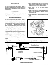
2. Expose timing belt:
a. Close seacock and drain seawater from hoses.
Remove seawater pump hoses at seawater
pump.
b. Remove two screws to release seawater pump
bracket.
c. Remove housing enclosing ignition coil.
d. Remove seawater pump from camshaft pulley.
e. Remove timing belt cover (belt guard).
NOTE
To reduce force needed to rotate crankshaft,
remove the spark plugs.
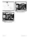
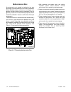
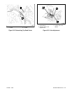
3. Using a ratchet wrench on the crankshaft nut,
rotate the crankshaft clockwise (as viewed from
engine end) until No. 1 cylinder is at the top of its
compression stroke and the ‘T’ mark on flywheel is
aligned with the triangle symbol on the engine
block. See Figure 3-22. The compression stroke is
the period between the closing of the intake valve
and the opening of the exhaust valve. The marks
define the TDC (top dead center) point where both
intake and exhaust valves will be closed.
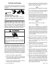
4. Insert feeler gauge between rocker arm and
exhaust valve for No. 1 cylinder. If necessary,
adjust screw so that very slight drag is felt on the
feeler gauge as it is withdrawn. Loosen the
adjusting screw locknut and turn the adjusting
screw to obtain the specified clearance. Retighten
the locknut while holding the adjusting screw. See
Figure 3-23. Recheck the valve clearance after
tightening the locknut. Repeat step for intake valve
of No. 1 cylinder.
5. Rotate crankshaft 360 degrees clockwise and set
valve clearances on No. 2 cylinder.
6. Reassembly of timing belt components:
a. Install timing belt cover (belt guard).
b. Install seawater pump to camshaft pulley.
c. Install housing for ignition coil.
d. Mount seawater pump bracket using two
screws.
e. Install seawater pump hoses to seawater pump.
Open seacock.
7. With mating surfaces clean and gasket properly
aligned, install rocker arm cover and screws.
Remove ratchet wrench from crankshaft nut.